Flying capacitor charging device and flying capacitor three-level chopper circuit

A technology of flying capacitors and charging devices, which is applied in the direction of output power conversion devices, electrical components, regulating electrical variables, etc.

Active Publication Date: 2019-11-01
ZHUZHOU CSR TIMES ELECTRIC CO LTD
View PDF8 Cites 20 Cited by
  • Summary
  • Abstract
  • Description
  • Claims
  • Application Information

AI Technical Summary

Problems solved by technology

[0003] In order to make the flying capacitor three-level chopper circuit output three levels, it is necessary to set the flying capacitor C f The voltage is controlled at half the intermediate DC voltage (that is, 1 / 2 the power supply voltage). Specifically, when the flying capacitor three-level chopper circuit starts, it will pass the first charging module 02 to the flying capacitor C f and support capacitance C d Perform the first precharge so that the flying capacitor C f The voltage reaches half the intermediate DC voltage, and the support capacitor C d The voltage at both ends reaches the power supply voltage E. At this time, the three-level chopper circuit of the flying capacitor enters the standby state. In the standby state, considering the leakage current discharge of the flying capacitor itself, and in actual circuit applications, it is necessary to detect the flying capacitor Transcapacitance C f The voltage of the flying capacitor is involved in the control, and a voltage detection circuit is connected in parallel at both ends of the flying capacitor. Therefore, when the standby time is long enough, the flying capacitor continues to discharge, and when the voltage at both ends drops below a certain value, it will cause the first switch. Switch tube V 01 , Diode D 01 and the switching tube V in the fourth switch 04 , Diode D 04 The withstand voltage exceeds the safe range, so that the switch tube V 01 , Diode D 01 and switch V 04 , Diode D 04 Overvoltage breakdown, if the switch tube V is increased 01 , Diode D 01 and switch V 04 , Diode D 04 The voltage level of the flying capacitor three-level chopper circuit is no longer the advantage of low voltage stress for the switching tube, and at the same time, the flying capacitor three-level chopper circuit is sacrificed in high switching frequency, high voltage and high power occasions. superiority

Method used


Image

  • Flying capacitor charging device and flying capacitor three-level chopper circuit
  • Flying capacitor charging device and flying capacitor three-level chopper circuit
  • Flying capacitor charging device and flying capacitor three-level chopper circuit

Examples


Embodiment Construction

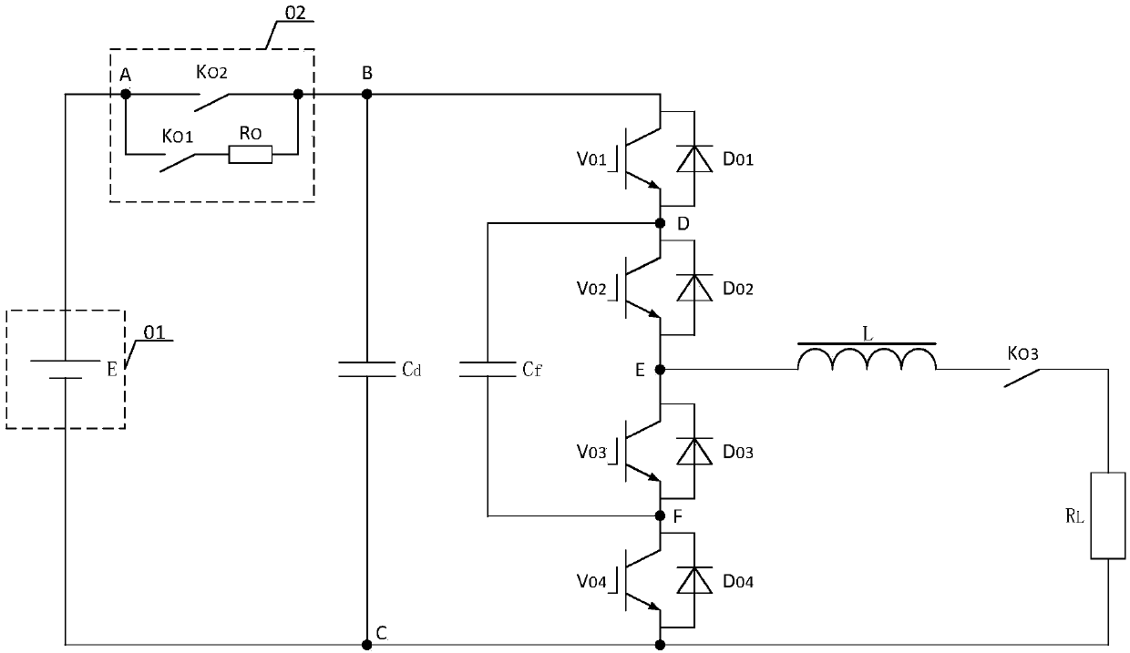
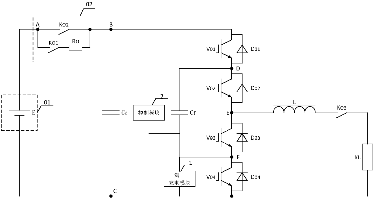
[0038] The core of the present invention is to provide a flying capacitor charging device and a flying capacitor three-level chopper circuit. Carry out secondary charging to keep the voltage of the flying capacitor within the normal variation range, thereby ensuring that the voltages borne by the switching tubes and diodes in the first switch, the second switch, the third switch, and the fourth switch are all in a safe range Within, so as to give full play to the advantages of the flying capacitor three-level chopper circuit.

[0039] In order to make the purpose, technical solutions and advantages of the embodiments of the present invention clearer, the technical solutions in the embodiments of the present invention will be clearly and completely described below in conjunction with the drawings in the embodiments of the present invention. Obviously, the described embodiments It is a part of embodiments of the present invention, but not all embodiments. Based on the embodimen...


PUM


Abstract

The invention discloses a flying capacitor charging device and a flying capacitor three-level chopper circuit. The flying capacitor charging device comprises a second charging module connected to theflying capacitor three-level chopper circuit, and a control module connected with the flying capacitor for detecting the voltage value of the flying capacitor, when the detected voltage value of the flying capacitor is smaller than a first preset value, the second charging module is controlled to charge the flying capacitor, and when the detected voltage value of the flying capacitor is greater than a second preset value, the second charging module is controlled to stop charging the flying capacitor. The flying capacitor in the flying capacitor three-level chopper circuit in a standby state ischarged through the flying capacitor charging device, the voltage of the flying capacitor is maintained within a normal variation range, that is, near half intermediate DC voltage, the voltage withstood by switching transistors and diodes in a first switch, a second switch, a third switch and a fourth switch is further ensured to be in a safe range, and the advantages of the flying capacitor three-level chopper circuit can be fully utilized.

Description

technical field [0001] The invention relates to the field of chopper circuits, in particular to a flying capacitor charging device and a flying capacitor three-level chopper circuit. Background technique [0002] The flying capacitor three-level chopper circuit has the advantages of being able to select switching tube devices with lower voltage levels, increasing the switching frequency, and reducing the size and cost of chopper inductors, and is widely used in high-voltage and high-power occasions. Generally, the flying capacitor three-level chopper circuit refers to figure 1 As shown, including power supply 01, first charging module 02, supporting capacitor C d , flying capacitor C f , the first switch, the second switch, the third switch, the fourth switch, the chopping inductor L, the output switch K 03 , load R L , wherein, the positive pole of the power supply 01 is connected to the first terminal of the first charging module 02, and the second terminal of the firs...

Claims


Application Information

Patent Timeline
Patent Type & Authority Applications(China)
IPC IPC(8): H02M3/158H02M1/32
CPCH02M1/32H02M3/158
Inventor 宋乾儒翁星方李华林文彪唐龙谢湘剑叶文玉董其爱吴雪峰邹今换王雄陈洲明
Owner ZHUZHOU CSR TIMES ELECTRIC CO LTD
Why Eureka
Try Eureka