L-band dual-frequency high-power rectifier circuit

A rectifier circuit and high-power technology, which is applied in the field of L-band dual-frequency high-power rectifier circuit, can solve the problems of large loss, many design branches, complex structure, etc., and achieve the effect of improving rectification efficiency and power capacity

Active Publication Date: 2019-11-01
CHINA INFOMRAITON CONSULTING & DESIGNING INST CO LTD
View PDF9 Cites 2 Cited by
  • Summary
  • Abstract
  • Description
  • Claims
  • Application Information

AI Technical Summary

Problems solved by technology

However, the structure is more complicated, there are more design branches, and the loss is larger

Method used


Image

  • L-band dual-frequency high-power rectifier circuit
  • L-band dual-frequency high-power rectifier circuit
  • L-band dual-frequency high-power rectifier circuit

Examples


Embodiment

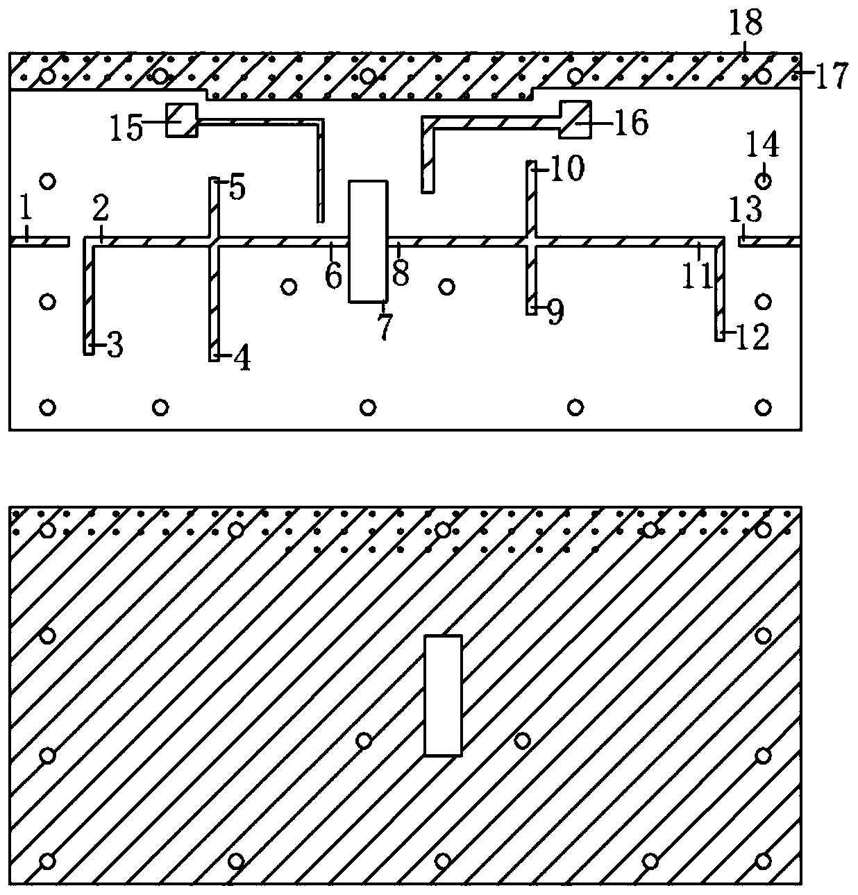
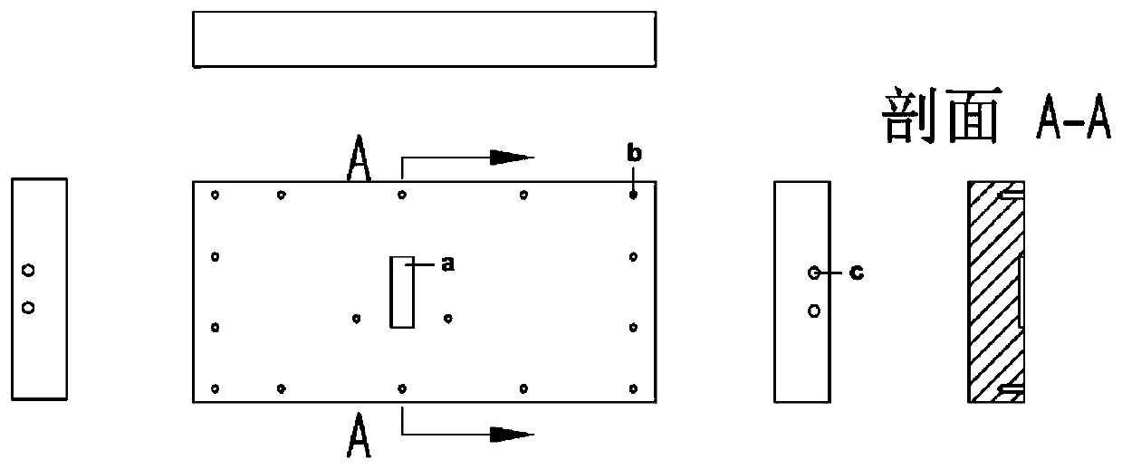
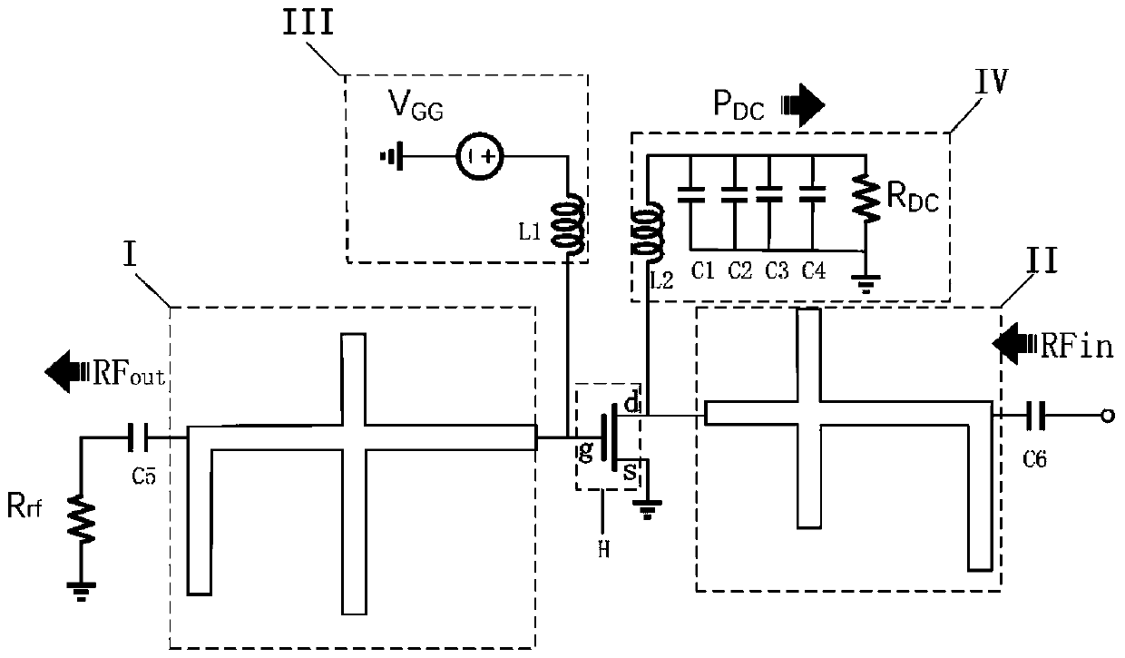
[0027] Such as figure 1 and figure 2 , an L-band dual-frequency high-power rectification circuit provided in this embodiment includes an upper PCB board and an aluminum base, and uses a GaN high electron mobility transistor (HEMT) as a rectification device to realize high-power rectification. The PCB board includes a microstrip matching circuit, a harmonic suppression circuit, a gate control circuit, an output filter circuit, grounding through holes, screw holes, and square through holes for rectifier devices. The aluminum base includes fixing screw holes for the upper PCB, grooves for rectifier components, and fixing screw holes for 50-ohm coaxial connectors on both sides.

[0028] GaN high electron mobility transistor HEMTs are mostly used as power amplifiers, and the conduction angle of the amplified signal is controlled by controlling the gate voltage to make the amplifier work in different states. When it is used as a class E or class F power amplifier with a low gate ...


PUM


Abstract

The invention provides an L-band dual-frequency high-power rectifier circuit .The L-band dual-frequency high-power rectifier circuit includes an upper PCB, wherein the PCB includes a microstrip matching circuit II, a harmonic suppression circuit I, a gate control circuit III and an output filter circuit IV, wherein the microstrip matching circuit II, the harmonic suppression circuit I, the gate control circuit III and the output filter circuit IV are respectively connected with a high electron mobility transistor. An RF signal is inputted from a drain d through a matching circuit and is rectified by the high electron mobility transistor H, the RF signal and a DC signal are superimposed and outputted by the drain d, a DC signal is outputted through a low-pass filter circuit, the RF signal is outputted by a gate g and is finally outputted to a RF load through the harmonic suppression circuit, the harmonic signal is reflected back to a rectifier device through the harmonic suppression circuit and continues to participate in rectification, and thereby the effect of improving rectification efficiency is achieved.

Description

technical field [0001] The invention relates to the technical field of radio frequency circuits, in particular to an L-band dual-frequency high-power rectification circuit. Background technique [0002] The charging system designed by microwave wireless power transmission technology is equivalent to a power transmission channel, which transmits the power energy at the entrance of the channel to the electric load at the exit of the channel. Compared with the traditional energy transmission method based on cables, wireless energy transmission technology does not require complex cable equipment, has the advantages of small footprint, saving transmission equipment, etc., and it can still play its role in complex and harsh environments. Functions, such as the power supply problem of the capsule inside the medical equipment, under normal circumstances, the patient needs to take out the capsule for battery replacement, but the wireless energy transmission technology can be wireless...

Claims


Application Information

Patent Timeline
Patent Type & Authority Applications(China)
IPC IPC(8): H02M7/217H02M7/00H02M1/14H02M1/08
CPCH02M1/08H02M1/14H02M7/003H02M7/217H02M1/0038
Inventor 毕丹宏
Owner CHINA INFOMRAITON CONSULTING & DESIGNING INST CO LTD
Why Eureka
Try Eureka