
Method for improving uniformity of plating surface of PCB pattern

A graphic electroplating and copper plating technology, applied in electrical components, printed circuits, printed circuit manufacturing, etc., can solve the problems of laser holes that cannot be filled, insufficient contact, uneven substrate plating thickness, etc., and achieve reasonable additive composition and concentration. , Increase the exchange capacity, avoid the effect of rough copper plating

Active Publication Date: 2019-11-01
清河电子科技(山东)有限责任公司
View PDF12 Cites 3 Cited by
  • Summary
  • Abstract
  • Description
  • Claims
  • Application Information

AI Technical Summary

Problems solved by technology

[0003](1) There is no special transfer fixture, so that the substrate graphics are directly in contact with the equipment, resulting in foreign matter sticking to the substrate, resulting in disconnection, gaps and hole plugging;
[0004](2) There is no plasma treatment, so that the surface of the seed copper layer and copper protection dry film is not in sufficient contact with the chemical solution, resulting in uneven copper plating and disconnection;
[0005](3) There is no auxiliary cathode or the setting is unreasonable, resulting in uneven plating thickness at the center and periphery of the substrate, or burrs on the edge of the substrate;
[0006](4) The spray device in the copper plating tank is unreasonably set up, resulting in the laser hole not being filled or a depression;
[0007](5) Unreasonable setting of additive composition and concentration in copper plating solution, resulting in rough copper plating, laser hole depression and uneven board surface

Method used


Image

  • Method for improving uniformity of plating surface of PCB pattern
  • Method for improving uniformity of plating surface of PCB pattern
  • Method for improving uniformity of plating surface of PCB pattern

Examples


Embodiment Construction

[0043] The present invention will be described in further detail below through specific embodiments and in conjunction with the accompanying drawings.

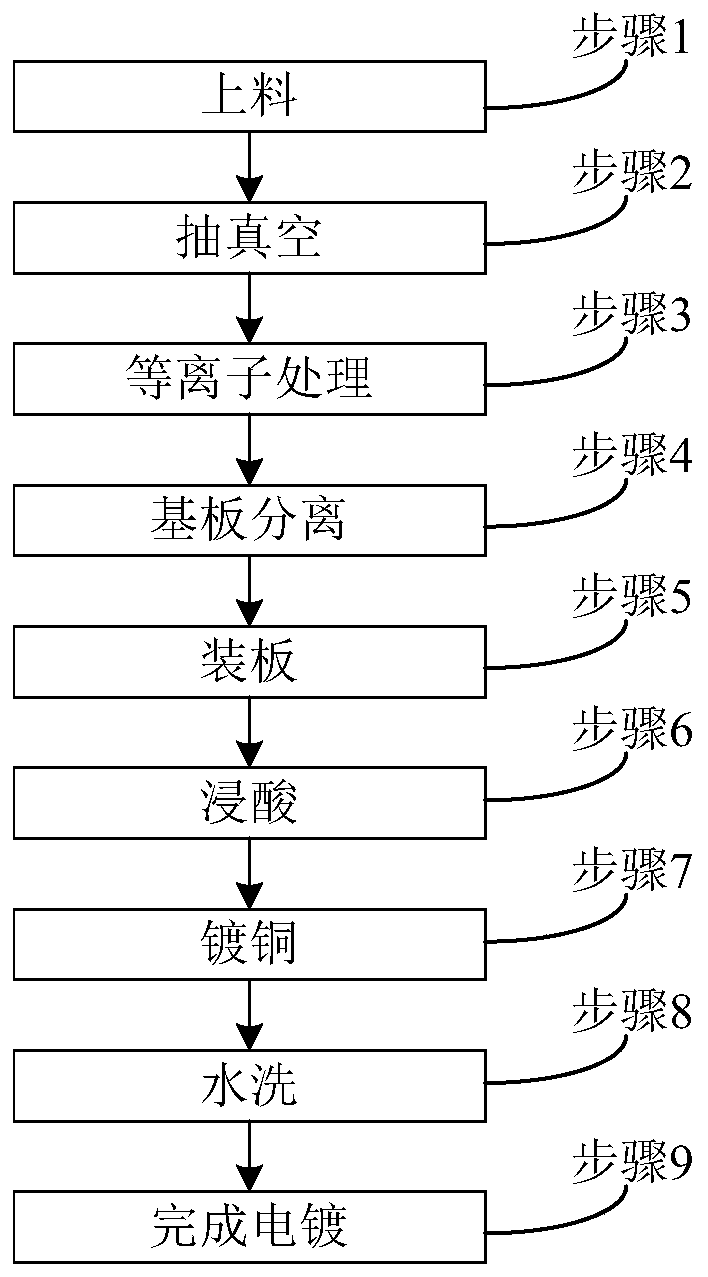
[0044] Such as figure 1 As shown, a method for improving the uniformity of PCB pattern plating surface described in the embodiment of the present invention mainly includes the steps of feeding, vacuuming, plasma treatment, substrate separation, board loading, pickling, copper plating, and water washing. .

[0045] The specific flow of each step will be described in detail below.

[0046] Step 1, loading: put the developed PCB substrate 2 into the jig 1, and transfer the jig 1 to the pre-processing device.

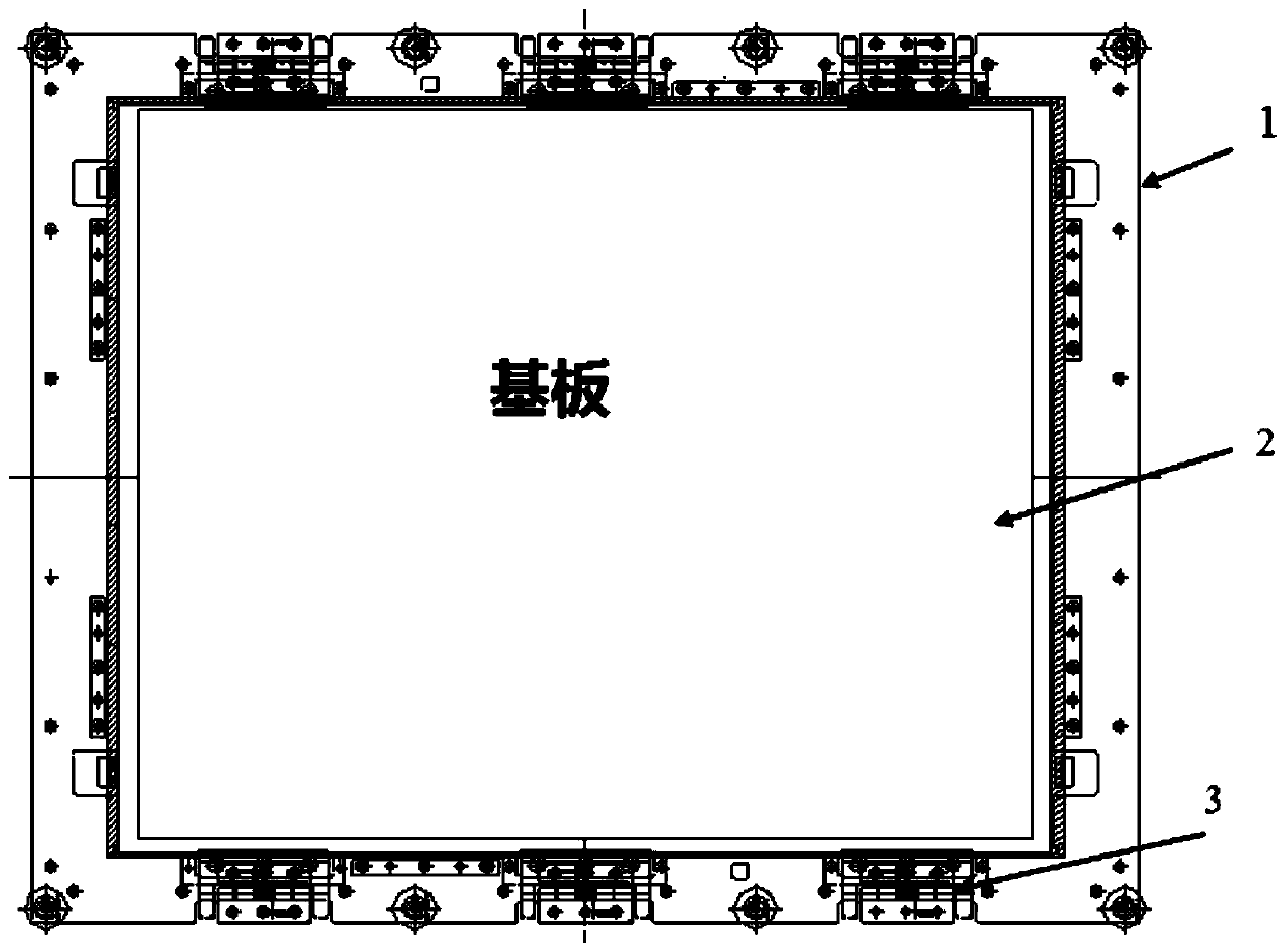
[0047] Such as figure 2 As shown, the jig 1 is a return-shaped structure, the PCB substrate 2 is placed in the middle of the jig 1, and the two opposite edges inside the jig 1 are respectively provided with a plurality of clamping devices 3, and the two edges of the PCB substrate 2 pass through A plurality of clamping ...


PUM


Abstract

The invention discloses a method for improving the uniformity of plating surface of a PCB pattern. The method comprises the steps of: the step 1, placing a developed substrate into a jig and transferring the jig to a pretreatment device; the step 2, vacuuming the pretreatment device; the step 3, performing plasma treatment of the pretreatment device; the step 4, transferring the jig to a jig disengaging device to separate the substrate from the jig; the step 5, vertically installing the substrate on a hanging tool, and arranging an auxiliary cathode at the edge of the PCB substrate; the step 6, putting the substrate into a 10% of sulfuric acid for 7 min; the step 7, configuring a copper plating solution, putting the copper plating solution into a copper plating bath, and immersing the substrate into the copper plating bath for copper plating; the step 8, removing the substrate from the copper plating bath, and performing four-level water washing; and the step 9, completing plating. Themethod provided by the invention can form thick copper layers with uniform thickness in the board surface and the laser hole.

Description

technical field [0001] The invention relates to the technical field of PCB, in particular to a method for improving the uniformity of the electroplating surface of a PCB pattern. Background technique [0002] PCB pattern electroplating is to use the method of electroplating to thicken the copper layer on the board surface and in the hole, and make the laser hole completely filled with copper to form an interlayer conductor. The existing graphic electroplating process has the following deficiencies due to the unreasonable process method: [0003] (1) There is no special transfer fixture, so that the substrate graphics are directly in contact with the equipment, resulting in foreign matter sticking to the substrate, resulting in disconnection, gaps and blocked holes; [0004] (2) There is no plasma treatment, so that the surface of the seed copper layer and the copper protection dry film are not in sufficient contact with the chemical solution, resulting in uneven copper plat...

Claims


Application Information

Patent Timeline
Patent Type & Authority Applications(China)
IPC IPC(8): H05K3/18
CPCH05K3/181
Inventor 盛利召郭晓玉
Owner 清河电子科技(山东)有限责任公司
Learn More