

Signal shaping device, shaping termination device, signal shaping method, and optical transmission method
A signal shaping and terminating device technology, applied in transmission systems, digital transmission systems, electromagnetic wave transmission systems, etc., can solve problems such as circuit installation problems, achieve the effect of simple structure and improve noise resistance
- Summary
- Abstract
- Description
- Claims
- Application Information
AI Technical Summary
Problems solved by technology
Method used
Image

Examples
Embodiment approach 1
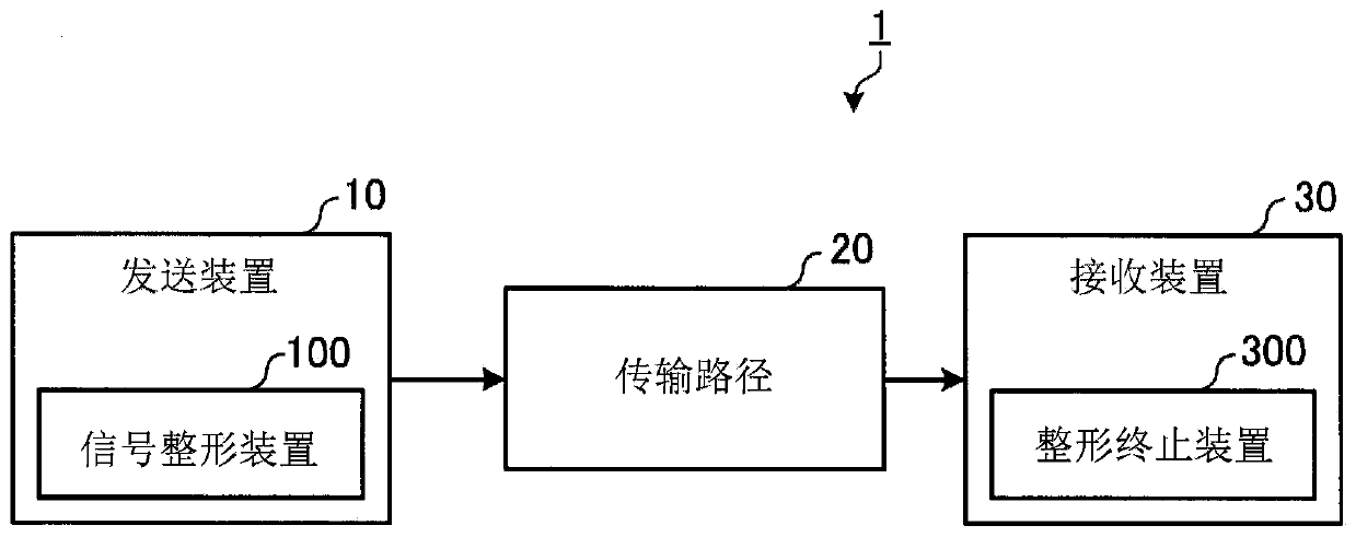
[0039] figure 1 It is a diagram showing the configuration of the shaped signal transmission system 1 according to Embodiment 1 of the present invention. The shaped signal transmission system 1 has a transmitting device 10 , a transmission path 20 and a receiving device 30 . The transmitting device 10 has a signal shaping device 100 , and the receiving device 30 has a shaping and terminating device 300 . The signal shaped by the signal shaping device 100 of the transmitting device 10 is transmitted to the receiving device 30 via the transmission path 20 , and returns to the state before shaping in the shaping terminating device 300 .
[0040]Regarding the method of shaping the signal, two methods are mentioned. The first method is a method called forward connection in which signal shaping is performed after error correction encoding and terminated before error correction decoding. The second method is a method called reverse connection in which signal shaping is performed be...
Embodiment approach 2
[0067] In Embodiment 1 described above, an example of performing forward connection processing in which signal shaping processing is performed after error correction encoding and signal shaping processing is terminated before error correction decoding is performed. In Embodiment 2, an example of performing reverse connection processing in which signal shaping processing is performed before error correction coding and signal shaping processing is terminated after error correction decoding will be described. Hereinafter, the same reference numerals will be attached to the same parts as those in Embodiment 1 to omit description, and the parts different from Embodiment 1 will be mainly described.
[0068] Figure 9 It is a diagram showing the configuration of a signal shaping device 100B according to Embodiment 2 of the present invention. The signal shaping device 100B includes a shaping processing unit 120 , an error correction coding unit 110 , and a symbol mapping unit 130 . ...
Embodiment approach 3
[0073] The configuration of the shaped signal transmission system 1 according to Embodiment 3 of the present invention is the same as that of Embodiment 1, and therefore description thereof will be omitted. Embodiment 3 is different from Embodiment 1 in that, in addition to selection information S, detection information P, which is a parity bit for error detection of selection information S, is added to the shaping block.
[0074] Figure 12 It is a diagram showing detection information P added by the signal shaping device 100 according to Embodiment 3 of the present invention. exist Figure 12 In the example shown, the candidate block of type1 is selected in the first block BL1, the candidate block of type2 is selected in the second block BL2, and the candidate block of type2 is selected in the third block BL3. A candidate block of type1 is selected among the four blocks BL4. Therefore, the value of the selection information S1 of the block BL1 is "0", the value of the sel...
PUM
 Abstract
Description
Claims
Application Information