
Circular saw

The technology of a circular saw and a rotor is applied to a circular saw. It can solve the problems of anti-blocking ability of electric tools and the difficulty of user experience to meet the needs, so as to achieve the effect of optimal control

Active Publication Date: 2019-11-05
NANJING CHERVON IND
View PDF15 Cites 1 Cited by
  • Summary
  • Abstract
  • Description
  • Claims
  • Application Information

AI Technical Summary

Problems solved by technology

Under heavy load conditions, the anti-stall capability and user experience of existing electric tools are difficult to meet the requirements

Method used

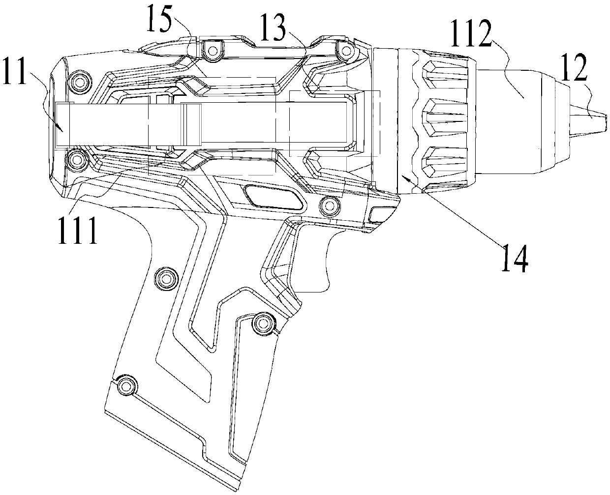
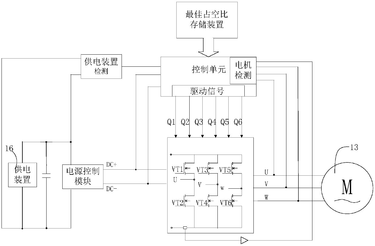
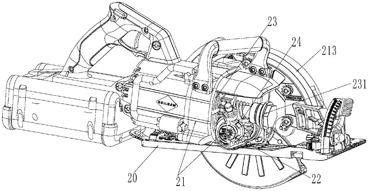

Image

  • Circular saw
  • Circular saw
  • Circular saw

Examples


Embodiment Construction

[0035] The present invention will be specifically introduced below in conjunction with the accompanying drawings and specific embodiments.

[0036] The motor control method and system provided by the present invention can be applied to most hand-held electric tools. It is only necessary to obtain the duty cycle corresponding to different working conditions based on the analysis of the characteristic parameter V of the power supply device and / or the characteristic parameter x of the motor. The duty cycle corresponding to x is used to control the driving circuit to drive the motor to operate, so as to realize the maximum inrush current of the electric tool and the optimization of the maximum output torque of the electric tool.

[0037] The specific embodiments of the present invention will be described below by taking three typical electric tools as examples.

[0038] In the first embodiment of the present invention, combining figure 1 The mechanical structure of the provided el...


PUM


Abstract

The invention discloses a circular saw. According to the circular saw, the duty ratio under different working conditions is determined according to a characteristic parameter V of a power supply device of the circular saw and the analysis of the rotating speed n of a motor, and a driving circuit is controlled by the duty ratio to drive the motor to operate. According to the circular saw, only theduty ratio is calculated, circuit hardware or a mechanical structure of an electric tool does not need to be changed, the motor can be optimized and controlled by adjusting the duty ratio, and therefore optimization of the working performance such as output torque of the electric tool is achieved.

Description

technical field [0001] The invention relates to the field of electric tools, in particular to a circular saw. Background technique [0002] Existing electric tools can be powered by a battery pack and drive a motor to run through a drive circuit. However, the current power tools, especially the hand-held power tools based on 1P battery packs, are difficult to control the inrush current of the battery pack and the output torque of the motor under heavy load. [0003] Existing electric tools, especially circular saws or electric drills, have a maximum inrush current as high as 100A or more in a locked-rotor state. High inrush current will seriously damage the power supply device of the electric tool, such as the battery pack, thereby affecting the safety of the electric tool. [0004] Therefore, for safety reasons, existing electric tools are equipped with an overload protection device, but the device will directly shut off the motor when the heavy load state of the electric...

Claims


Application Information

Patent Timeline
Patent Type & Authority Applications(China)
IPC IPC(8): B23B45/02B23D45/16B24B23/02B25F5/00H02P27/08
CPCB25F5/00H02P6/08Y02P70/10
Inventor 陈伟鹏杨德中李文成
Owner NANJING CHERVON IND
Learn More