
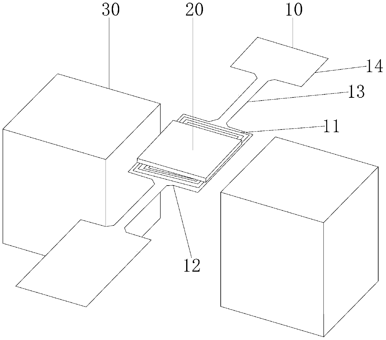
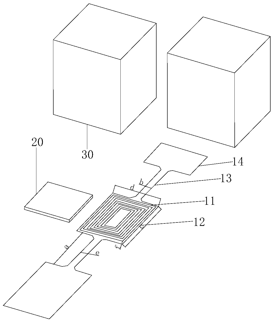
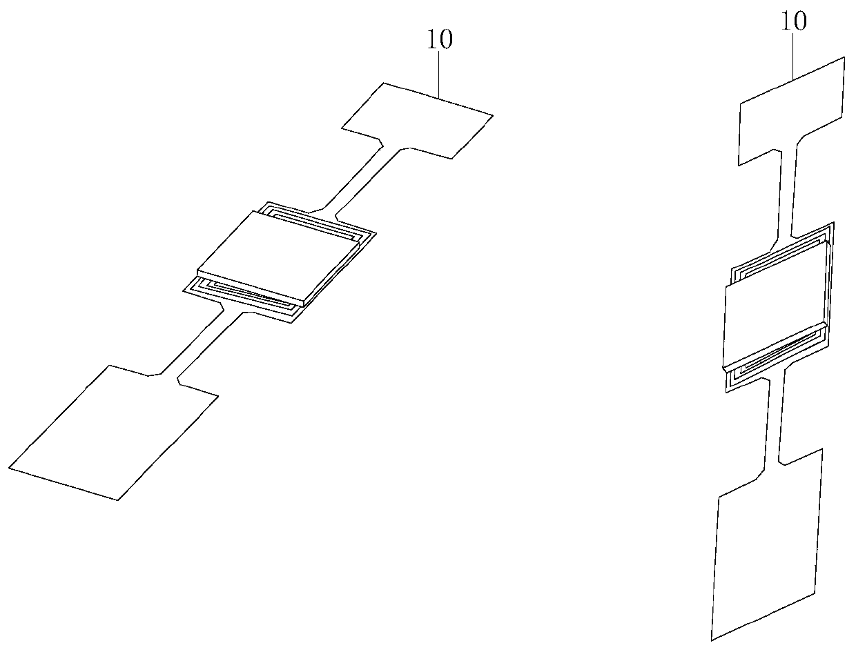
Flexible PCB electromagnetic micromirror, scanner and laser marking/carving machine

An electromagnetic micro-mirror, flexible technology, applied in the fields of laser marking/engraving and micro-mirrors, can solve the problems of small optical aperture, unsuitable for laser marking/engraving applications, low flatness, etc., to improve marking accuracy, eliminate Drift/creep error, low cost effect

Inactive Publication Date: 2019-11-05
贺思源 +1
View PDF7 Cites 2 Cited by
  • Summary
  • Abstract
  • Description
  • Claims
  • Application Information

AI Technical Summary

Problems solved by technology

However, most existing MEMS micromirrors are not suitable for laser marking / engraving applications due to their small optical aperture (<1mm) and low flatness (radius of curvature<1m)

Method used


Image

  • Flexible PCB electromagnetic micromirror, scanner and laser marking/carving machine
  • Flexible PCB electromagnetic micromirror, scanner and laser marking/carving machine
  • Flexible PCB electromagnetic micromirror, scanner and laser marking/carving machine

Examples


Embodiment Construction

[0044] In order to make the purpose, technical solutions and advantages of the embodiments of the present invention clearer, the technical solutions in the embodiments of the present invention will be clearly and completely described below in conjunction with the drawings in the embodiments of the present invention. Obviously, the described embodiments It is a part of embodiments of the present invention, but not all embodiments. Based on the embodiments of the present invention, all other embodiments obtained by persons of ordinary skill in the art without making creative efforts belong to the protection scope of the present invention.

[0045] In the description of the present invention, it should be noted that the terms "center", "upper", "lower", "left", "right", "vertical", "horizontal", "inner", "outer" etc. The indicated orientation or positional relationship is based on the orientation or positional relationship shown in the drawings, and is only for the convenience of...


PUM

PropertyMeasurementUnit
pore sizeaaaaaaaaaa
sizeaaaaaaaaaa
magnetic flux densityaaaaaaaaaa

Abstract

The invention discloses a flexible PCB electromagnetic micromirror, a scanner and a laser marking / carving machine. The flexible PCB electromagnetic micromirror comprises a flexible PCB structure, a lens and external magnets; the flexible PCB structure comprises a flexible layer and a coil layer, and the flexible layer is usually a polyimide layer; the lens is adhered to the flexible PCB structure;the external magnets are arranged around the flexible PCB structure and are used for generating a magnetic field; and during being used, voltage / current is applied to a coil of the coil layer, and the coil perpendicular to the magnetic field generates force for driving the flexible PCB structure and the lens to rotate. The flexible PCB electromagnetic micromirror has the characteristics of beinglarge in quasi-static rotation angle, large in optical aperture, high in lens surface flatness and low in cost; the laser scanner can be manufactured on the basis of the flexible PCB electromagnetic micromirror, and the laser marking / carving machine can be manufactured on the basis of the laser scanner; and the marking / carving machine has the advantages of being low in cost, convenient to carry and the like.

Description

technical field [0001] The invention relates to the technical fields of micromirror and laser marking / engraving, in particular to a flexible PCB electromagnetic micromirror, a scanner and a laser marking / engraving machine. Background technique [0002] Laser marking / engraving machines use a focused laser beam to remove top layers or alter the surface properties of target materials. They are widely used in marking / engraving identification numbers, logos and barcodes etc. in industries such as automotive, medical equipment, textile, electronics and semiconductor. Compared with other marking technologies (such as electrochemical etching, dot impact and inkjet), laser marking technology has many advantages, such as: can eliminate burrs and waviness to obtain higher surface quality of the finished product, non-contact method, and can Mark on materials that are difficult to mark with other techniques. A laser marking / engraving machine consists of two main parts: a laser source a...

Claims


Application Information

Patent Timeline
Patent Type & Authority Applications(China)
IPC IPC(8): B23K26/082B23K26/362
CPCB23K26/082B23K26/362
Inventor 贺思源卡尔·马克思·裴瑞雅瑟米
Owner 贺思源
Learn More