Cleaning equipment for plastic recycling
A technology for cleaning equipment and plastic recycling, which is applied in the direction of plastic recycling, recycling technology, etc., can solve problems such as unfavorable human health, and achieve the effects of convenient work, reasonable division of labor, and safe and convenient use
- Summary
- Abstract
- Description
- Claims
- Application Information
AI Technical Summary
Problems solved by technology
Method used
Image

Examples
Embodiment 1
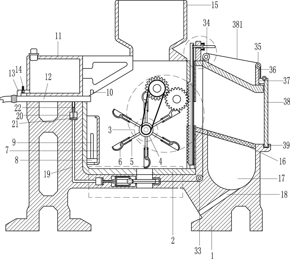
[0022] see figure 1 and figure 2 , a cleaning device for plastic recycling, including a mounting frame 1, a cleaning frame 2, a cleaning device, a floating blocking device, a liquid inlet device, a hopper 15, a mesh plate 16 and a pulling blocking device, and a cleaning frame 2 is installed in the middle of the mounting frame 1 The cleaning frame 2 is equipped with a cleaning device that cleans the plastic by rotating. The cleaning frame 2 is provided with a floating blocking device that prevents the liquid from entering by buoyancy. Liquid inlet device, a hopper 15 is installed on the top of the cleaning frame 2, a mesh plate 16 is arranged in the right part of the mounting frame 1, and a second groove 17 is opened on the mounting frame 1 below the mesh plate 16, and the installation frame below the second groove 17 A water outlet 18 is provided on the frame 1, and the lower part of the mounting frame 1 is provided with a pull blocking device that prevents liquid from enter...
Embodiment 2
[0025] see figure 1 , the floating blocking device includes a frame body 7, a floating plate 8 and a first baffle plate 9, and a frame body 7 is installed on the left side wall of the cleaning frame 2, and the cleaning frame 2 is connected with the frame body 7 by bolts, and the frame body A floating plate 8 is provided in the sliding type of the 7, and a first baffle 9 is provided on the top of the floating plate 8, and a first groove 10 is provided on the mounting frame 1 above the first baffle 9. Specifically, when the pulling blocking device is closed, the water with disinfectant flows into the cleaning frame 2, and the water level rises, driving the floating plate 8 to move upward along the frame body 7, and the floating plate 8 drives the first baffle plate 9 to move upward, The first baffle 9 is inserted into the first groove 10 to block the liquid inlet device, and the water no longer flows out. When the used water needs to be discharged, the pull blocking device is op...
Embodiment 3
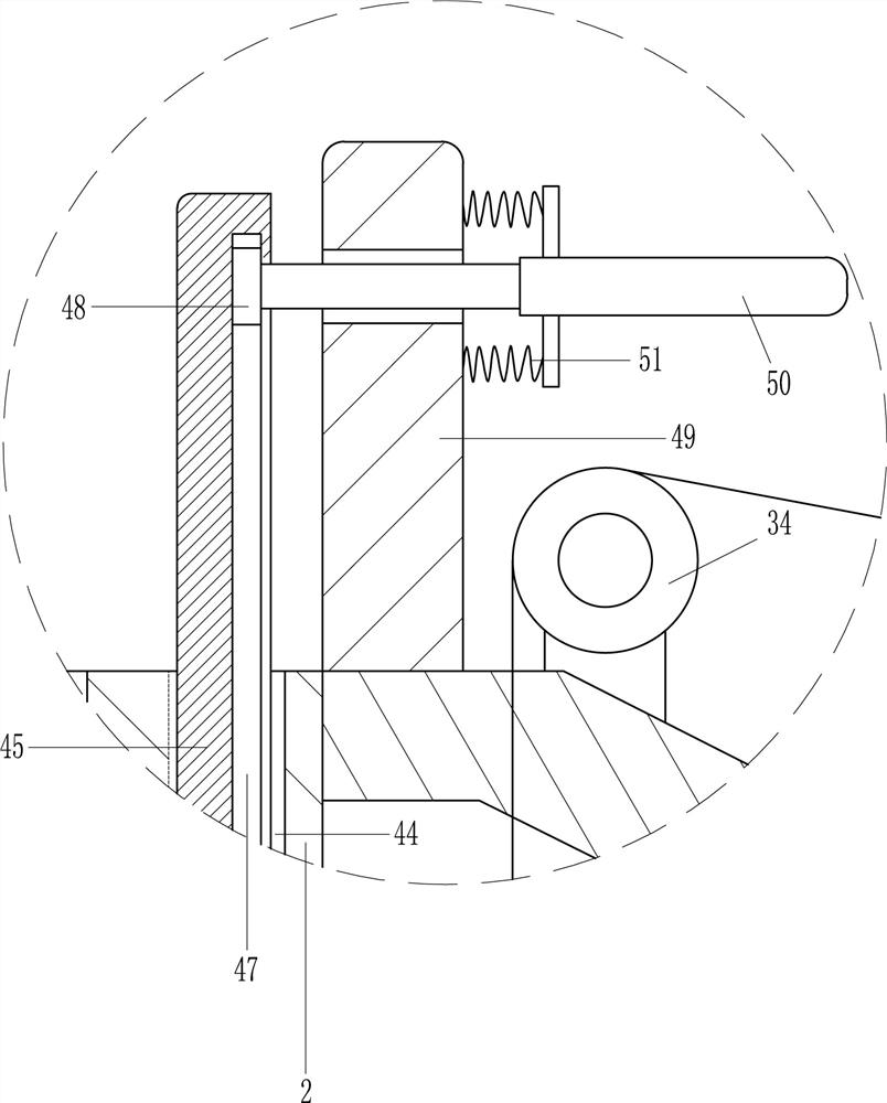
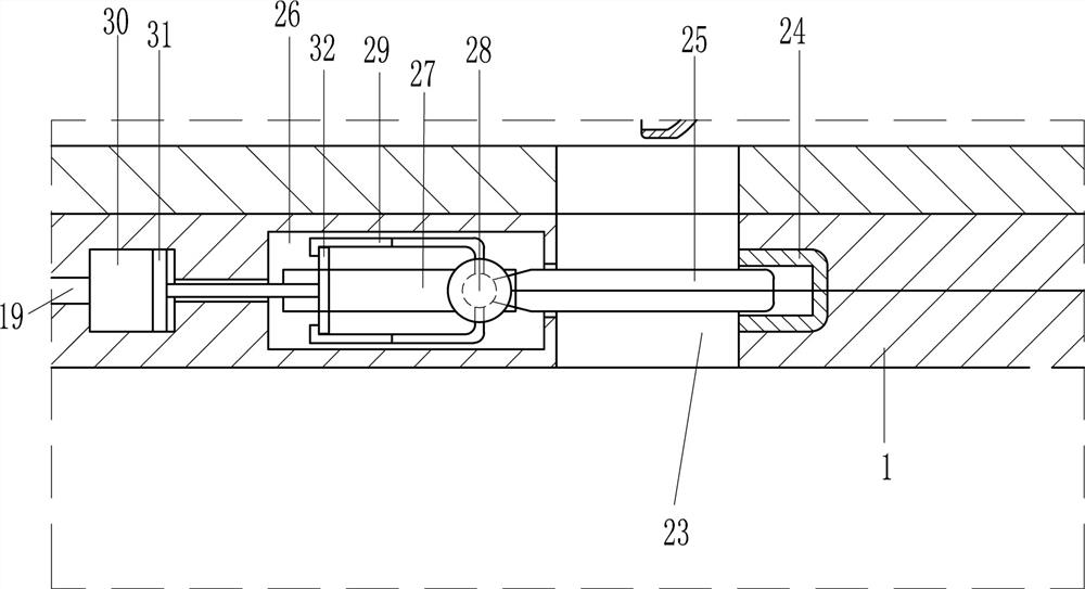
[0028] see figure 1 and figure 2 , on the basis of Embodiment 1 and Embodiment 2, the pulling blocking device includes an intake pipe 19, a first piston 21, a second baffle 22, a rubber sleeve 24, a third baffle 25, a round shaft 28, and an L-shaped telescopic Plate 29, second piston 31 and push plate 32, there is a first cavity 20 in the left part of the installation frame 1, the first cavity 20 is provided with a first piston 21 sliding up and down, and the top of the first piston 21 is provided with a second Baffle plate 22, the mounting frame 1 bottom has water outlet 23, is provided with rubber cover 24 on the mounting frame 1 on the right side in water outlet 23, has the 3rd groove 26 on the mounting frame 1 of water outlet 23 left sides, the 3rd groove 26, the first There is a word hole 27 on the mounting frame 1 on the front side of the three grooves 26, and a round shaft 28 is slidably provided in the word hole 27, and the round shaft 28 is provided with a third baf...
PUM
 Abstract
Description
Claims
Application Information
 - R&D
- Intellectual Property
- Life Sciences
- Materials
- Tech Scout
- Unparalleled Data Quality
- Higher Quality Content
- 60% Fewer Hallucinations
Browse by: Latest US Patents, China's latest patents, Technical Efficacy Thesaurus, Application Domain, Technology Topic, Popular Technical Reports.
© 2025 PatSnap. All rights reserved.Legal|Privacy policy|Modern Slavery Act Transparency Statement|Sitemap|About US| Contact US: help@patsnap.com