Magnetic suspension door

A magnetic levitation and magnetic pole technology, applied in the field of magnetic levitation, can solve problems such as uneven road surface at the door, mechanical friction between the door body and the track, and inconvenient opening and closing of the door

Pending Publication Date: 2019-11-05
长春市苏伟磁悬浮技术研究所
View PDF6 Cites 1 Cited by
  • Summary
  • Abstract
  • Description
  • Claims
  • Application Information

AI Technical Summary

Problems solved by technology

[0005] The purpose of the present invention is to provide a magnetic levitation door to solve the problems of uneven road surface at the door, inconvenient opening and closing of the door, and mechanical friction between the door body and the track in the existing sliding door technology.

Method used


Image

  • Magnetic suspension door
  • Magnetic suspension door
  • Magnetic suspension door

Examples


Embodiment 1

[0070] The structure of this embodiment 1 will be described in detail below in conjunction with the figures.

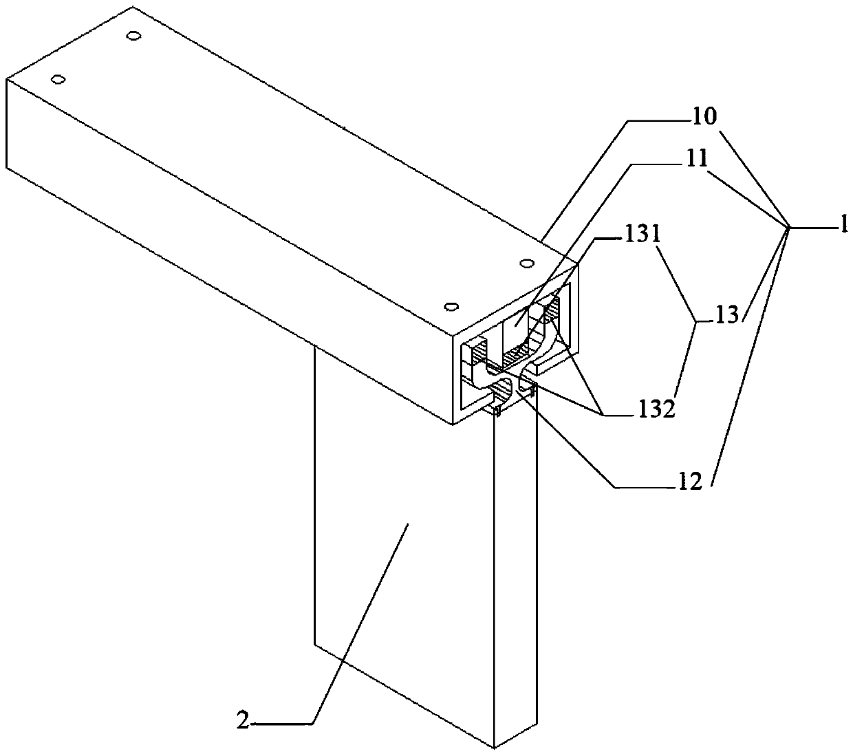
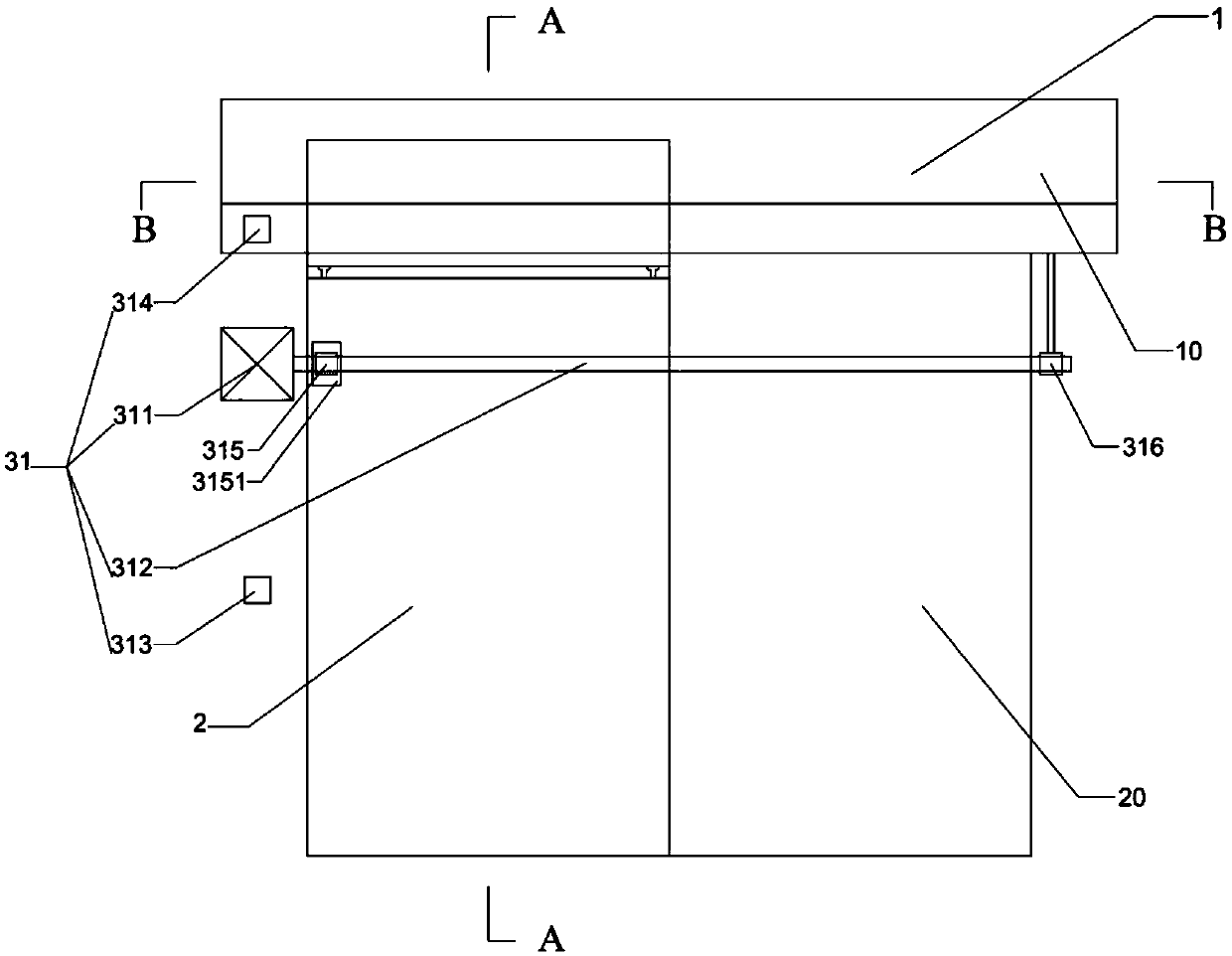
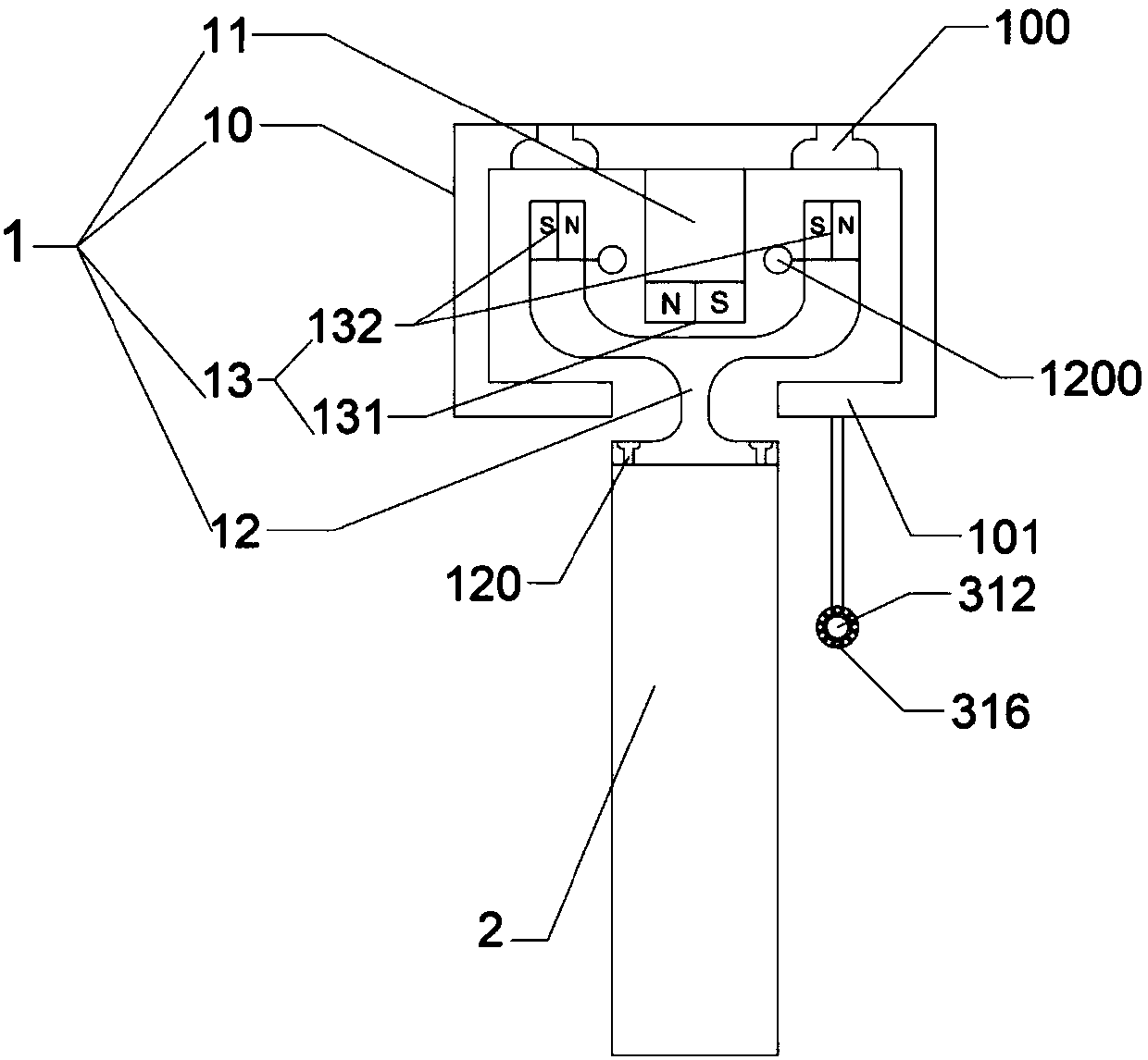
[0071] refer to figure 1 , figure 2 , image 3 with Figure 4 The magnetic suspension door involved in the present embodiment 1 is a single magnetic suspension door driven by a single rail, and the magnetic suspension door includes a magnetic suspension track 1 and a moving door 2 arranged under the magnetic suspension track 1, and the magnetic suspension track 1 includes a track beam 10 , a fixed track 11, a suspension slider 12 and a permanent magnet 13, the track beam 10 is a box beam with an open bottom, and the fixed track 11 is fixed on the lower surface of the box beam top plate; the permanent magnet 13 includes a fixed permanent The magnet array 131 and the suspension permanent magnet array 132, the fixed permanent magnet array 131 and the suspension permanent magnet array 132 are arranged at equal intervals vertically to form a rectangular parallelepiped ...

Embodiment 2

[0088] The structure of this embodiment 2 will be described in detail below in conjunction with the figures.

[0089] refer to Image 6 , Figure 7 with Figure 8 The maglev door involved in this embodiment is a single-track, electromagnetically driven single maglev door. The maglev door includes a maglev track 1 and a moving door 2 arranged under the maglev track 1. The maglev track 1 includes a track beam 10, Fixed track 11, suspension slider 12 and permanent magnet 13, described track beam 10 is the box beam of bottom opening, and described fixed track 11 is fixed on the lower surface of box beam top plate; Described permanent magnet 13 comprises fixed permanent magnet Array 131 and suspended permanent magnet array 132, described fixed permanent magnet array 131 and described suspended permanent magnet array 132 are all arranged to form rectangular parallelepiped permanent magnet array by vertical tracks of the permanent magnet vertical tracks of a plurality of completely...

Embodiment 3

[0105] The structure of the third embodiment will be described in detail below in conjunction with the figures.

[0106] refer to Figure 10 , Figure 11 with Figure 12 The magnetic suspension door involved in this embodiment is a double-track, electromagnetically driven single magnetic suspension door. The magnetic suspension door includes a magnetic suspension track 1 and a moving door 2 arranged under the magnetic suspension track 1. The magnetic suspension track 1 includes a track beam 10, Fixed track 11, suspension slider 12 and permanent magnet 13; Described track beam 10 is the rectangular section beam that has rectangular groove 101 at the bottom, and described fixed track 11 comprises first fixed track 111 and second fixed track 112, described The first fixed track 111 and the second fixed track 112 are laid in parallel on both sides of the rectangular groove 101 on the bottom surface of the track beam 10; the permanent magnet 13 includes a fixed permanent magnet a...


PUM


Abstract

The invention discloses a magnetic suspension door, and relates to the technical field of magnetic suspension. The magnetic suspension door comprises a magnetic suspension rail and a movable door under the magnetic suspension rail; the magnetic suspension rail comprises a rail beam, a suspension slider and permanent magnets; a fixed rail is fixed on the lower surface of the rail beam; the permanent magnets comprise a fixed permanent magnet array and a suspension permanent magnet array; the fixed permanent magnet array is arranged on the bottom of the fixed rail and the suspension permanent magnet array is arranged in the suspension slider to achieve homopolar repulsion between the suspension permanent magnet array and the fixed permanent magnet array; the suspension slider is suspended below the fixed rail through the repulsive action of the suspension permanent magnet array and the fixed permanent magnet array; the movable door is fixed at the lower end of the suspension slider; and the magnetic suspension door further comprises a driving device. The magnetic suspension door does not need to be provided with a rail on the ground, does not need to be opened or closed manually, doesnot have mechanical friction between the rail and a door body, and is a proper magnetic suspension door.

Description

technical field [0001] The invention relates to the technical field of magnetic suspension, in particular to a magnetic suspension door. Background technique [0002] The door can be used not only as the eaves decoration of the residence, but also as an independent building. It can be traced back to the branch cover at the entrance of the natural cave in the primitive society. With the development of civilization, the old products of the door are gradually eliminated, and the new products of the door are quickly applied. Especially after the 20th century, the development of science and technology is changing with each passing day, and the development of the door has undergone several changes. Modern doors are full of beautiful things in eyes, and there are many types. At present, the doors on the market can be divided into wooden doors, plastic steel doors, aluminum alloy doors, glass doors, plastic doors, etc. according to the materials. [0003] From the industrial revolu...

Claims


Application Information

Patent Timeline
Patent Type & Authority Applications(China)
IPC IPC(8): E06B3/46E05D15/06E05F15/652E05F15/70E05F15/60H02N15/00
CPCE05D15/0652E05F15/60E05F15/652E05F15/70E05Y2900/132E06B3/4636H02N15/00
Inventor 苏伟
Owner 长春市苏伟磁悬浮技术研究所
Why Eureka
Try Eureka