Compressor control method and device and computer readable storage medium

A control method and compressor technology, applied in pump control, machine/engine, mechanical equipment, etc., can solve the problem of over-current in the compressor, and achieve the effect of preventing over-current

Active Publication Date: 2019-11-05
GD MIDEA HEATING & VENTILATING EQUIP CO LTD +1
View PDF7 Cites 4 Cited by
  • Summary
  • Abstract
  • Description
  • Claims
  • Application Information

AI Technical Summary

Problems solved by technology

[0006] The main purpose of the present invention is to provide a compressor control method, device and computer-readable storage medium, aiming t

Method used


Image

  • Compressor control method and device and computer readable storage medium
  • Compressor control method and device and computer readable storage medium
  • Compressor control method and device and computer readable storage medium

Examples


no. 1 example

[0107] Based on the first embodiment, a second embodiment of the compressor control method of the present invention is proposed. In this embodiment, step S140 includes:

[0108] Step S141, determining the first target D-axis voltage based on the three-phase current;

[0109] Step S142, determining a first target Q-axis voltage based on the limit voltage and the first target D-axis voltage;

[0110] Step S143, controlling the operation of the compressor based on the first target D-axis voltage and the first target Q-axis voltage.

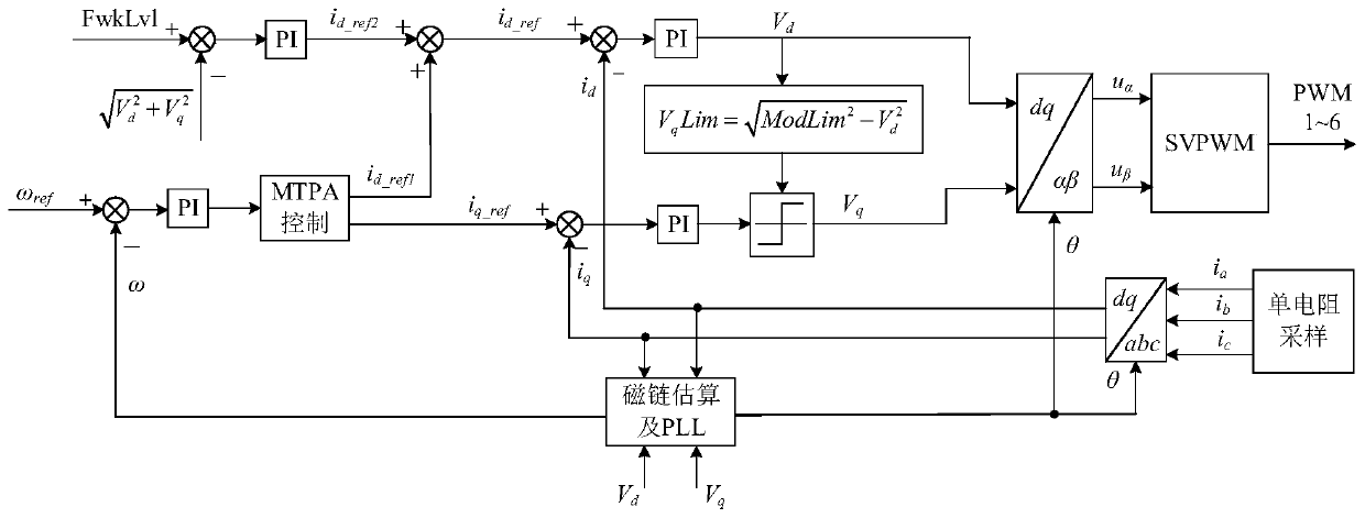
[0111] refer to image 3 , in this embodiment, first determine the first target D-axis voltage V based on the three-phase current d , and then through the first target D-axis voltage V d and the limit voltage ModLim to determine the first target Q-axis voltage V q , and based on the first target D-axis voltage V d and the first target Q-axis voltage V q Control the operation of the compressor, and specifically perform coordinate transformation ...

no. 2 example

[0113] Based on the second embodiment, a third embodiment of the compressor control method of the present invention is proposed. In this embodiment, step S141 includes:

[0114] Step S1411, based on the three-phase current, obtain the first D-axis current and the first Q-axis current of the compressor at the current moment, obtain the second target D-axis voltage and the second target Q-axis voltage at the previous moment, and acquiring an angular frequency based on the first D-axis current and the first Q-axis current, a second target D-axis voltage, and a second target Q-axis voltage;

[0115] Step S1412, determining a second D-axis current based on the angular frequency, and determining a third D-axis current based on the command modulation voltage, the second target D-axis voltage, and the second target Q-axis voltage;

[0116] Step S1413: Determine a first target D-axis voltage based on the third D-axis current, the second D-axis current, and the first D-axis current.

...

no. 3 example

[0121] Based on the third embodiment, a fourth embodiment of the compressor control method of the present invention is proposed. In this embodiment, step S142 includes:

[0122] Step S1421, determining a target Q-axis current based on the angular frequency, and determining a first Q-axis voltage based on the first Q-axis current and the target Q-axis current;

[0123] Step S1422, determining a second Q-axis voltage based on the first target D-axis voltage and the limit voltage;

[0124] Step S1423: Determine the first target Q-axis voltage based on the first Q-axis voltage and the second Q-axis voltage.

[0125] In this example, refer to image 3 , first determine the target Q-axis current i based on the angular frequency q_ref , based on the first Q-axis current i q and the target Q-axis current i q_ref , to obtain the second Q-axis current, and perform PI control on the second Q-axis current to obtain the first Q-axis voltage. Based on the first target D-axis voltage an...


PUM


Abstract

The invention discloses a compressor control method. The method comprises the following steps that a bus current of the compressor is acquired, wherein the bus current comprises a three-phase current;whether a target phase current greater than a preset current exists in the three-phase current is determined, and if the target phase current greater than the preset current exists in the three-phasecurrent, a first preset voltage is set as a limit voltage corresponding to the voltage vector of the compressor; and the compressor is controlled to operate on the basis of the limit voltage so as toreduce the operation frequency of the compressor. The invention further discloses a compressor control device and a computer readable storage medium. According to the compressor control method, the automatic frequency reduction of the compressor can be realized before the compressor is subjected to an over-current, and the situation that the compressor is subjected to the over-current due to thefact that the frequency of the compressor is not timely reduced when the bus voltage is reduced.

Description

technical field [0001] The present invention relates to the field of motor technology, in particular to a compressor control method, device and computer-readable storage medium. Background technique [0002] Because the voltage stability of power grids in different countries and regions varies greatly, especially in some less developed countries and rural areas, the power grid stability is worse, and the grid voltage fluctuates very quickly (some fluctuations are milliseconds or even lower), which may cause bus voltage Instantaneous drop, frequent shutdown of the air conditioner due to grid voltage instability. [0003] At present, the frequency limit protection mainly relies on the voltage and current frequency limit logic of the main control chip of the air conditioner, but it takes a long time (including communication delay) for the main control chip to detect the voltage / current and issue the frequency limit command, and the voltage drops instantly. Sometimes the main c...

Claims


Application Information

Patent Timeline
IPC IPC(8): F04B51/00F04B49/06F04B39/00
CPCF04B39/00F04B49/06F04B51/00
Inventor 彭国彬
Owner GD MIDEA HEATING & VENTILATING EQUIP CO LTD
Why Eureka
Try Eureka