One-way exhaust valve

A technology of one-way exhaust valve and exhaust cavity, which is applied in the direction of valve details, control valves, valve devices, etc., can solve the problems of small cross-sectional area of ​​exhaust holes, failure of valve design structure, failure of valve function, etc., and achieve the passage pressure Accurate value, reduce the overall weight, ensure the effect of stability

Pending Publication Date: 2019-11-05
北京平恩康汽车技术有限公司
View PDF0 Cites 3 Cited by
  • Summary
  • Abstract
  • Description
  • Claims
  • Application Information

AI Technical Summary

Problems solved by technology

[0004] At present, the bonnet of this kind of check valve is finished by metal parts processing technology, which cannot meet the design requirements of the air guide structure size, and the valve body and the valve shell are bonded to form a sealed state.
The cross-sectional area of ​​the exhaust hole on the inner wall of the valve is small, and the gas in the valve body cavity cannot be quickly discharged. The valve cover and the valve body are connected by threads, which is easy to loosen during use. When the airflow reaches the designed pressure, the spring begins to compress the value. The rubber pad rises with the airflow direction, and the airflow enters the valve body cavity, causing the valve to work in the abnormal design air pressure range, and the valve design structure fails; the position of the air guide hole is low, and rainwater or foreign matter easily enters the valve body cavity during the use of the vehicle and affects the performance of the valve. Normal operation causes valve function to fail

Method used


Image

  • One-way exhaust valve
  • One-way exhaust valve
  • One-way exhaust valve

Examples


Embodiment Construction

[0034] The following will clearly and completely describe the technical solutions in the embodiments of the present invention with reference to the accompanying drawings in the embodiments of the present invention. Obviously, the described embodiments are only some, not all, embodiments of the present invention. Based on the embodiments of the present invention, all other embodiments obtained by persons of ordinary skill in the art without making creative efforts belong to the protection scope of the present invention.

[0035] The purpose of the present invention is to provide a one-way exhaust valve to solve the problems in the prior art.

[0036] In order to make the above objects, features and advantages of the present invention more comprehensible, the present invention will be further described in detail below in conjunction with the accompanying drawings and specific embodiments.

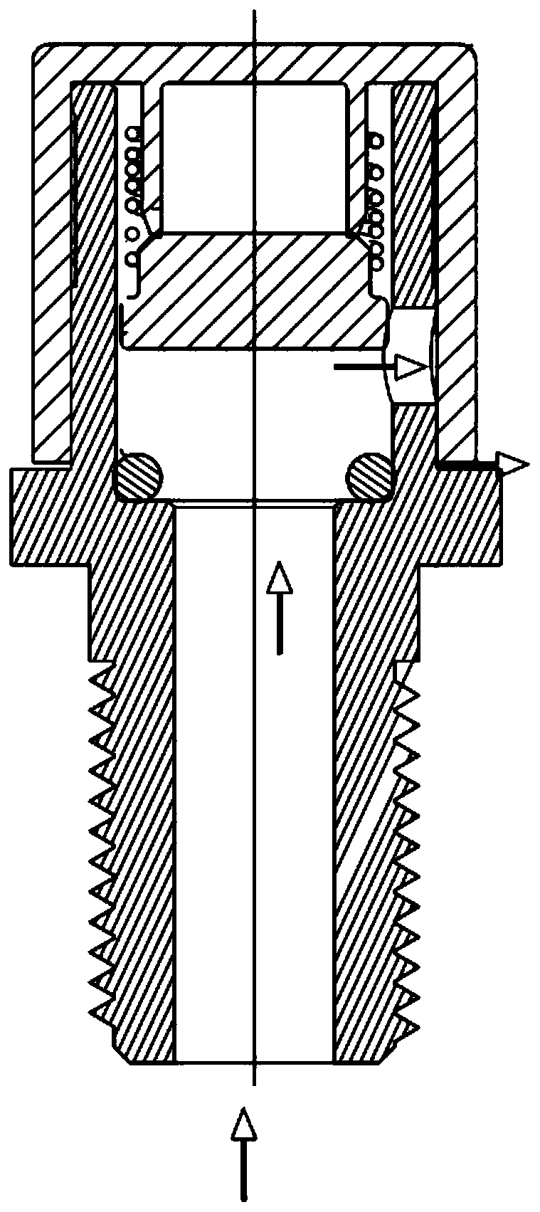
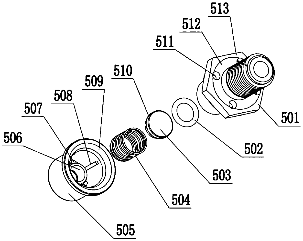
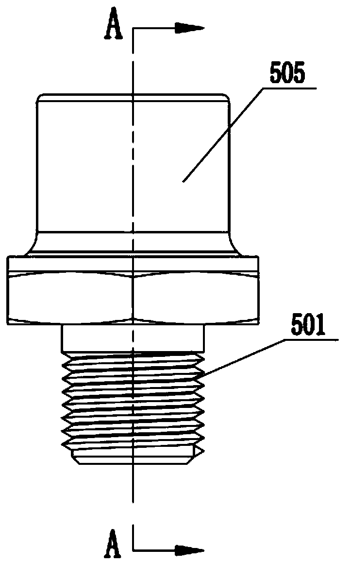
[0037] The invention provides a one-way exhaust valve, such as Figure 2-Figure 5 As sho...


PUM


Abstract

The invention discloses a one-way exhaust valve, comprising a valve body, a sealing ring, a valve core, a spring and a valve cover, wherein an assembly lug boss is arranged on the outer wall of the valve body, vent holes are distributed in the assembly lug boss in the circumferential direction, and the valve cover covers the top of the valve body and is riveted and fixed to the assembly lug boss;an annular cavity is formed between a spring guide seat and the inner cavity wall in the valve cover, a plurality of first sub-cavity ribs which are arranged radially are distributed at the top of theannular cavity circumferentially, and a first exhaust passage is formed between the adjacent first sub-cavity ribs; a plurality of second sub-cavity ribs which are arranged axially are distributed onthe inner wall of the cavity body of the valve cover circumferentially, and a second exhaust passage is formed between the adjacent second sub-cavity ribs and communicates with the vent holes. According to the one-way exhaust valve, the exhaust passages have large cross-sectional area and can quickly discharge gas; connection between the valve body and the valve cover is stable and not easy to loosen, the spring can be stably contracted according to the specified pressure, and the exhaust valve can be accurately opened; and the operating stability of the exhaust valve can also be ensured.

Description

technical field [0001] The invention relates to the technical field of exhaust valves for vehicles, in particular to a one-way exhaust valve. Background technique [0002] When the vehicle accelerates rapidly during driving, a large amount of gas will be generated in the transfer case to prevent the pressure in the cavity from being too high. To reduce the pressure in the cavity, a check valve must be installed to complete the pressure relief function. Check valves are generally installed in automobiles. The upper transfer case, front / rear bridge position, installed at the highest point of the assembly. [0003] The structure and working principle of the existing one-way valve are as follows: figure 1 As shown, the arrow in the figure indicates the airflow direction. When the pressure is generated in the transfer case, the airflow enters the valve body through the valve exhaust cavity. When the pressure reaches the designed range, the spring in the valve starts to compress,...

Claims


Application Information

Patent Timeline
Patent Type & Authority Applications(China)
IPC IPC(8): F16K15/12F16K27/02F16K27/08
CPCF16K15/12F16K27/0209F16K27/08
Inventor 陈坤罗相大李伟强谢荣荣余阳
Owner 北京平恩康汽车技术有限公司
Why Eureka
Try Eureka