Chirp spectral pattern cavity-less optical fiber Fabry-Perot filter and manufacturing method thereof

A manufacturing method and filter technology, applied in light guides, optics, instruments, etc., can solve problems such as low chirp rate, damage to chirp characteristics of interference spectrum, and low effective refractive index, etc., to achieve large chirp changes rate effect

Active Publication Date: 2019-11-05
JINAN UNIVERSITY
View PDF6 Cites 5 Cited by
  • Summary
  • Abstract
  • Description
  • Claims
  • Application Information

AI Technical Summary

Problems solved by technology

[0005] However, due to the existence of the cavity area, there will be two problems
First, since the effective refractive index does not vary greatly with the diameter in the two cone regions, the chirp rate of the interference spectrum is not very high
In addition, because the chirped gratings written in the two sections of the cone cannot guarantee complete symmetry, the wavele

Method used


Image

  • Chirp spectral pattern cavity-less optical fiber Fabry-Perot filter and manufacturing method thereof
  • Chirp spectral pattern cavity-less optical fiber Fabry-Perot filter and manufacturing method thereof
  • Chirp spectral pattern cavity-less optical fiber Fabry-Perot filter and manufacturing method thereof

Examples


Embodiment

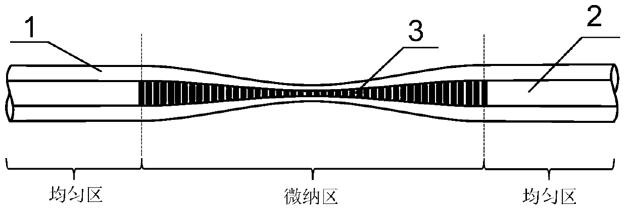
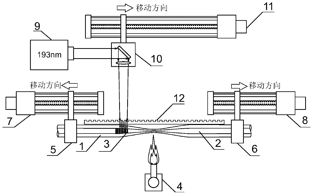
[0031] A chirped spectrum cavityless fiber Fabry-Perot filter, including a fused tapered multimode micro-nano fiber cladding 1, a multimode micro-nano fiber core 2 and continuously written equal-period Bragg gratings 3 parts. After continuously scanning and writing a long grating on the micro-nano transition region, although there is no cavity length in the formed structure, since the fiber micro-nano region can be regarded as the left and right parts centered on the thinnest position, the grating written on it It can also be two parts on the left and right. For a tiny grating segment with a certain diameter on the left side of the grating, there must be a tiny grating segment with the same diameter on the right side. The reflection wavelengths of the two are the same. The back and forth reflections between the small grating segments and finally form multi-beam interference. Similarly, multi-beam interference will also be formed in the tiny grating segment area inside the abo...


PUM


Abstract

The invention discloses a chirp spectral pattern cavity-less optical fiber Fabry-Perot filter. The filter is characterized in that the filter comprises a multi-mode micro-nano optical fiber cladding,a multi-mode micro-nano optical fiber core and a Bragg grating; the multi-mode micro-nano optical fiber cladding is an outermost layer. According to the along-axis cross section of the multi-mode micro-nano optical fiber cladding, transition is realized from a uniform region with a constant radius to a micro-nano region with a gradually-changed radius, and again transition is realized from the micro-nano region with the gradually-changed radius to the other uniform region with a constant radius. The multi-mode micro-nano optical fiber core is an inner layer and is covered by the multi-mode micro-nano optical fiber cladding. According to the along-axis cross section of the multi-mode micro-nano optical fiber core, transition is realized from a uniform region with a constant radius to a micro-nano region with a gradually-changed radius, and again transition is realized from the micro-nano region with the gradually-changed radius to the other uniform region with a constant radius. The Bragg grating is a continuously-inscribed and equal-period Bragg grating which covers all the micro-nano region of the multi-mode micro-nano optical fiber core. With the chirp spectral pattern cavity-less optical fiber Fabry-Perot filter provided by the invention adopted, a chirp spectral pattern which can change in a free spectral range can be realized within a relatively large wavelength range, anda relatively large chirp rate can be realized. The chirp spectral pattern cavity-less optical fiber Fabry-Perot filter has the advantages of compact structure and easiness in manufacture.

Description

technical field [0001] The invention relates to the research field of optical devices, in particular to a chirp spectrum type cavityless optical fiber Fabry-Perot filter and a manufacturing method thereof. Background technique [0002] The chirped spectral multi-wavelength filter is a multi-wavelength device with non-uniform wavelength intervals, which is often used in the field of chirped signal generation. For example, in pulse compression technology, the use of frequency-time mapping technology and chirped spectral The spectral shaping technology of the optical filter can obtain the frequency-swept microwave pulse signal. [0003] In order to realize the chirped spectrum fiber shaping filter device, a feasible solution is to cascade fiber Bragg gratings with different bandwidths and interferometric fiber devices with specially designed phases. For fiber Bragg gratings cascaded with different bandwidths, it is very difficult to write because the grating period and modulat...

Claims


Application Information

Patent Timeline
IPC IPC(8): G02B6/293
CPCG02B6/29316G02B6/29359
Inventor 曹元陆众王光英肖鹏冯新焕关柏鸥
Owner JINAN UNIVERSITY
Why Eureka
Try Eureka