
Display panel and display device

A display panel and display area technology, applied in optics, instruments, electrical components, etc., can solve problems such as poor touch control and easy erosion of fan-out lines, and achieve the effect of enhancing corrosion resistance and improving product reliability

Inactive Publication Date: 2019-11-05
XIAMEN TIANMA MICRO ELECTRONICS
View PDF7 Cites 14 Cited by
  • Summary
  • Abstract
  • Description
  • Claims
  • Application Information

AI Technical Summary

Problems solved by technology

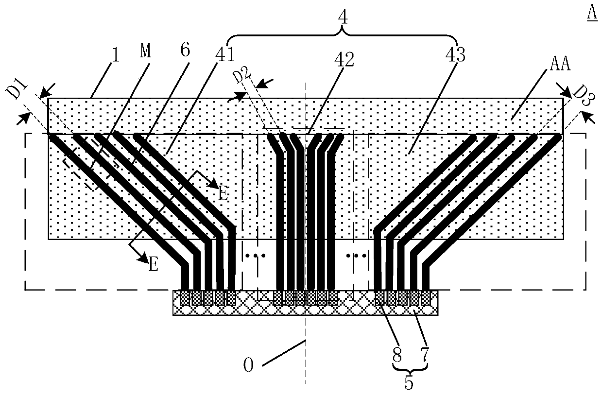
[0003] However, the improvement of display performance has put forward higher requirements for its structure, such as the continuous reduction of pixel unit size of ultra-high resolution display, accompanied by more data wiring, and touch display needs to add a large number of additional This makes the area between the display area of ​​the display panel and the integrated circuit in the display, that is, the wiring in the fan-out area (Fan-out area) too dense, coupled with the current display requirements for narrow borders, making The area of ​​the fan-out area of ​​the display panel is continuously reduced, and the distribution of the wiring is continuously denser, which makes the fan-out lines vulnerable to erosion and easy to cause poor touch control

Method used


Image

  • Display panel and display device
  • Display panel and display device
  • Display panel and display device

Examples


Embodiment Construction

[0027] Various exemplary embodiments of the present invention will now be described in detail with reference to the accompanying drawings. It should be noted that the relative arrangements of components and steps, numerical expressions and numerical values ​​set forth in these embodiments do not limit the scope of the present invention unless specifically stated otherwise.

[0028] The following description of at least one exemplary embodiment is merely illustrative in nature and in no way taken as limiting the invention, its application or uses.

[0029] Techniques, methods and devices known to those of ordinary skill in the relevant art may not be discussed in detail, but where appropriate, techniques, methods and devices should be considered part of the description.

[0030] In all examples shown and discussed herein, any specific values ​​should be construed as exemplary only, and not as limitations. Therefore, other instances of the exemplary embodiment may have differen...


PUM


Abstract

The invention discloses a display panel and a display device. The display panel includes a display area, and the display area includes multiple signal lines extending along a first direction and aligned along a second direction; a non-display area includes fan-out line wiring areas and a binding area, a fan-out line wiring area along a first direction locates between the display area and the binding area, multiple fan-out lines area are arranged in the fan-out line wiring area, an integrated chip and multiple bonding pads are arranged in the binding area, and signal lines are connected to thebonding pads by the fan-out lines, and the first fan-out line wiring area, a second fan-out line wiring area and a third fan-out line wiring area are aligned in turn along a second direction in the fan-out line wiring area. By the arrangement that the distance between the centers of two adjacent fan-out lines locating in the first fan-out line wiring area is longer than the distance between the centers of two adjacent fan-out lines locating in the second fan-out line wiring area, and the distance between the centers of two adjacent fan-out lines locating in the third fan-out line wiring area is longer than the distance between the centers of two adjacent fan-out lines locating in the second fan-out line wiring area, the display panel and the display device can enhance the corrosion resistance of the fan-out lines and improve the product reliability.

Description

technical field [0001] The present invention relates to the field of display technology, and more particularly, to a display panel and a display device. Background technique [0002] With the continuous development of display technology, display devices such as liquid crystal displays and organic light-emitting displays continue to emerge, becoming mainstream products in the display industry today, and are in the midst of rapid development and change. At the same time, consumers' requirements for displays are also increasing. Daily enhancements, such as ultra-high resolution displays, touch displays, and holographic displays, have become hot spots and important topics in the field of display research. [0003] However, the improvement of display performance has put forward higher requirements for its structure, such as the continuous reduction of pixel unit size of ultra-high resolution display, accompanied by more data wiring, and touch display needs to add a large number o...

Claims


Application Information

Patent Timeline
IPC IPC(8): G02F1/1345H01L27/32
CPCG02F1/1345G02F1/13458H10K59/10
Inventor 周秀峰伍黄尧周洪波骆晓东
Owner XIAMEN TIANMA MICRO ELECTRONICS
Features
  • Generate Ideas
  • Intellectual Property
  • Life Sciences
  • Materials
  • Tech Scout
  • Unparalleled Data Quality
  • Higher Quality Content
  • 60% Fewer Hallucinations
Learn More