Cooling assembly of linear motor rotor, linear motor rotor, linear motor and machine tool

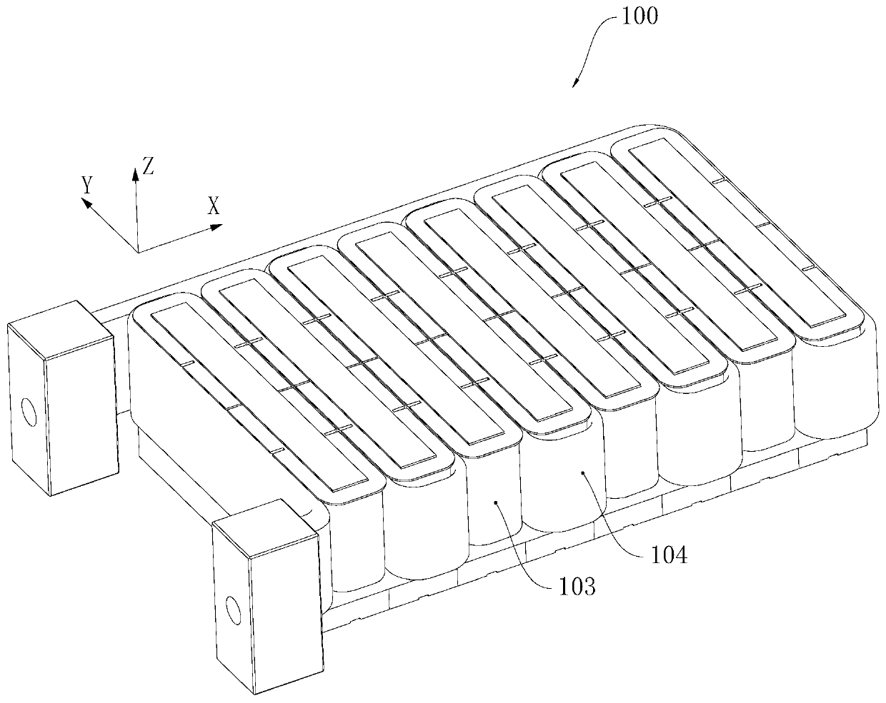
A technology for cooling components and linear motors, which is used in magnetic circuit rotating parts, metal processing machinery parts, maintenance and safety accessories, etc., and can solve the problem of uneven cooling of linear motor movers, large area of ​​coil winding 103, and linear motor movers. Problems such as poor regional cooling can avoid local poor cooling and improve the cooling effect.

Active Publication Date: 2019-11-05
GREE ELECTRIC APPLIANCES INC
View PDF5 Cites 1 Cited by
  • Summary
  • Abstract
  • Description
  • Claims
  • Application Information

AI Technical Summary

Problems solved by technology

[0003] Each coil winding 103 is surrounded by a U-shaped pipe section with an opening of the winding section 104 towards the Y-axis direction (positive or negative), and the coil winding 103 is cooled by the U-shaped pipe section, but the coil winding 103 The side wall corresponding to the U-shaped opening cannot be covered by the U-shaped pipe section, that is, each coil winding 103 has a side wall facing the Y-axis direction that cannot be covered by the winding section 104, and the coil winding 103 cannot be covered by the winding section 104 The area of ​​the winding section 104 is so large that it cannot be cooled by the surrounding winding section 104, resulting in that the area of ​​the coil winding 103 that is not covered by the winding section 104 cannot be well cooled, resulting in poor cooling of the linear motor mover part area, resulting in a straight line There is obvious uneven cooling of the motor mover, which affects the normal operation of the linear motor

Method used


Image

  • Cooling assembly of linear motor rotor, linear motor rotor, linear motor and machine tool
  • Cooling assembly of linear motor rotor, linear motor rotor, linear motor and machine tool
  • Cooling assembly of linear motor rotor, linear motor rotor, linear motor and machine tool

Examples


Embodiment 1

[0034] This example refers to figure 2 The coordinate system shown is described.

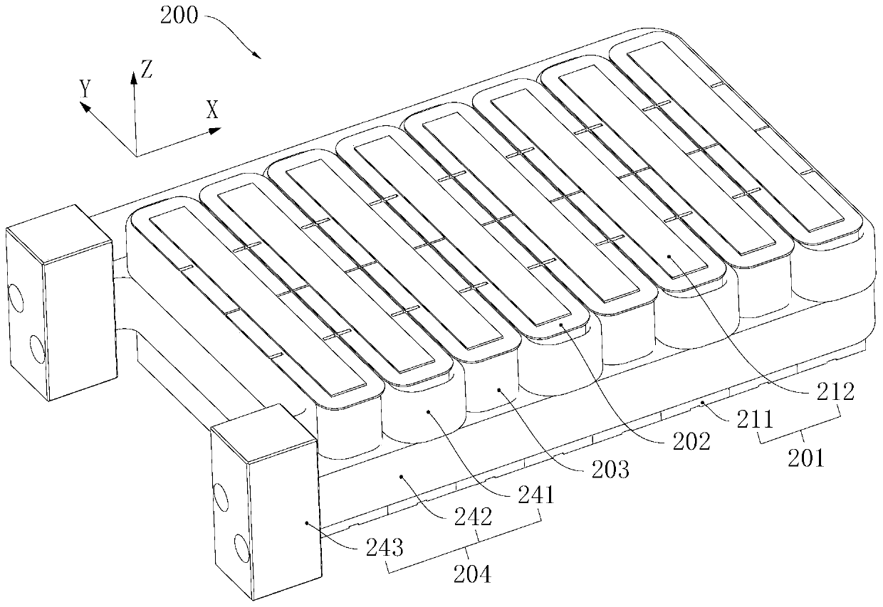
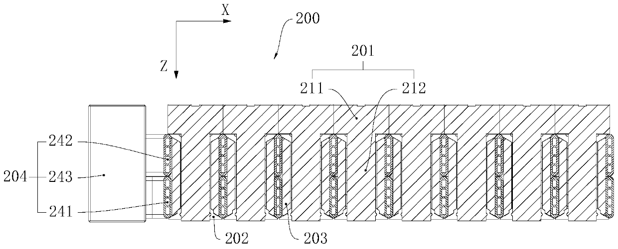
[0035] At least one feed system of the machine tool of this embodiment is driven by the linear motor of this embodiment. The linear motor of this embodiment includes a stator and a linear motor mover of this embodiment. Please refer to figure 2 and image 3 The linear motor mover of this embodiment includes a mover core 201 , an insulating frame 202 , a coil winding 203 and a cooling assembly 204 of this embodiment, and the cooling assembly 204 of this embodiment includes a cooling tube group and a cooling joint 243 .

[0036] Please refer to figure 2 and image 3 The mover core 201 has a main body 211 and a plurality of teeth 212 distributed along the X-axis direction, each tooth 212 protrudes from the main body 211 along the positive direction of the Z-axis, and the insulating skeleton 202 has a plurality of tooth sleeves, each The tooth sleeves are fixedly sheathed on each tooth portio...

Embodiment 2

[0044] Please refer to Figure 5 , in this embodiment, the first winding section 2412 communicates with the second straight section 2421 through the connector 244, the first cooling pipe 241 communicates with the second cooling pipe 242 in series, and the cooling joint 243 is independently provided with a liquid inlet channel and a liquid outlet The liquid inlet channel on the cooling joint 243 communicates with the first straight section 2411 , and the liquid outlet channel on the cooling joint 243 communicates with the second winding section 2422 . In this way, the cooling liquid flows through the first cooling pipeline 241 and the second cooling pipeline 242 sequentially, which can also achieve the purpose of uniformly cooling the linear motor mover.

[0045] Optionally, the series connection of the first cooling pipeline 241 and the second cooling pipeline 242 can also be that the first winding section 2412 and the second winding section 2422 are communicated through an ad...


PUM


Abstract

The invention provides a linear motor rotor, a linear motor rotor, a linear motor, a machine tool and a production method of the linear motor rotor, and relates to the field of the motor. The coolingassembly of the linear motor rotor comprises a cooling pipe group which comprises a first cooling pipeline and a second cooling pipeline. The first cooling pipeline is provided with a first winding section. The second cooling pipeline is provided with a second winding section. The first winding section and the second winding section serpentinely extend along a first direction. The first cooling pipeline and the second cooling pipeline are distributed along a third direction. The first direction and the third direction are perpendicular. The projection of the first winding section and the projection of the second winding section form a plurality of shadow rings distributed along the first direction through enclosing according to the projection along the third direction so that the cooling effect and the cooling uniformity of the linear motor rotor can be improved and the operation performance of the linear motor rotor can be improved.

Description

technical field [0001] The invention relates to the field of motors, in particular to a linear motor mover, a linear motor mover, a linear motor and a machine tool. Background technique [0002] Existing linear motors such as figure 1 As shown, the cooling pipeline of the linear motor mover has a winding section 104 extending in a serpentine shape. The winding section 104 of the cooling pipeline is sequentially wound on each coil winding 103 of the mover along the X-axis direction. Coolant is used to cool the linear motor mover. [0003] Each coil winding 103 is surrounded by a U-shaped pipe section with an opening of the winding section 104 towards the Y-axis direction (positive or negative), and the coil winding 103 is cooled by the U-shaped pipe section, but the coil winding 103 The side wall corresponding to the U-shaped opening cannot be covered by the U-shaped pipe section, that is, each coil winding 103 has a side wall facing the Y-axis direction that cannot be cove...

Claims


Application Information

Patent Timeline
IPC IPC(8): H02K3/24H02K1/32B23Q5/00B23Q11/12
CPCB23Q5/00B23Q11/127H02K1/32H02K3/24
Inventor 谢芳焦雷张海斌张智超郑立章赖奕霖
Owner GREE ELECTRIC APPLIANCES INC
Why Eureka
Try Eureka