Rod Material Transfer Device

A transfer device and material technology, applied in food science, application, tobacco, etc., can solve problems such as low efficiency, chain movement speed limit, equipment failure, etc., to achieve the effect of improving production efficiency, ensuring production quality, and reducing failure

Active Publication Date: 2022-04-19
XIANGYANG SHENGUAN MECHANICAL & ELECTRICAL TECH CO LTD
View PDF14 Cites 0 Cited by
  • Summary
  • Abstract
  • Description
  • Claims
  • Application Information

AI Technical Summary

Problems solved by technology

The above method has the following disadvantages: the chain needs to be lubricated during use, and oil stains are easy to adhere to the rod-shaped material; after a period of use, the chain wears out and becomes longer, which easily causes interference between the teeth and the inner wall of the material groove, resulting in equipment failure and damage. At the same time, the movement speed of the chain is limited, which limits the production efficiency
[0004] However, the above-mentioned transmission device that converts the circular motion of the rod-shaped product into a linear motion has the following disadvantages: it is realized by using a cam and chain mechanism, and the efficiency is low. It is necessary to provide a transmission device that efficiently converts the circular motion of the rod-shaped material into a linear motion.

Method used


Image

  • Rod Material Transfer Device
  • Rod Material Transfer Device

Examples


Embodiment 1

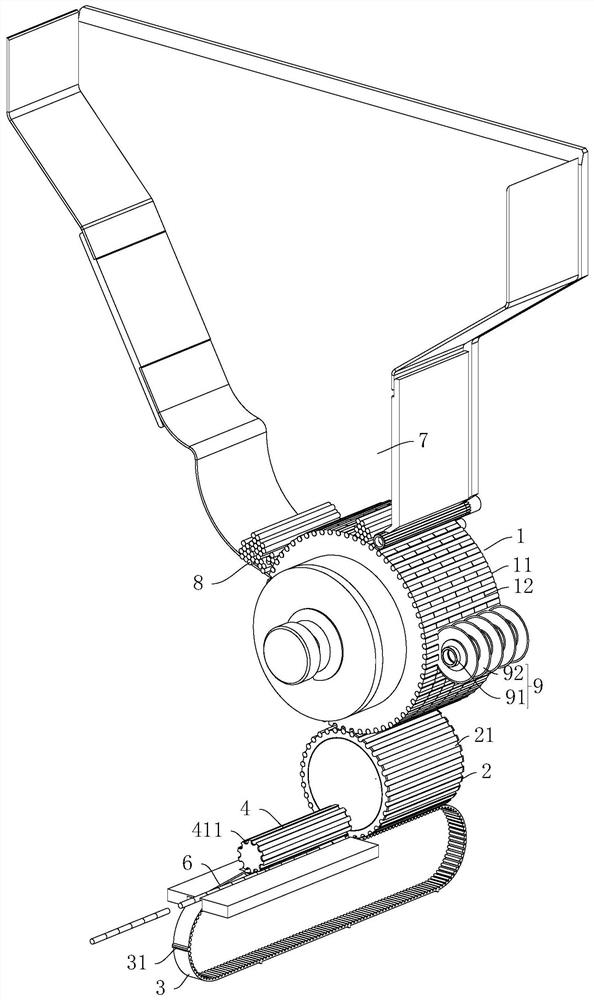
[0033] Embodiment 1: rod-shaped material transfer device, such as figure 1 As shown, including a frame, the frame is provided with a rotating feeding wheel 1 and a material storage bucket 7, and the material storage bucket 7 is filled with a rod-shaped material 8. The lower end of the material storage bucket 7 is provided with an opening, and the upper end of the feeding wheel 1 inside the opening. There are multiple material grooves 11 on the circumferential surface of the feed wheel 1, the length of the material grooves 11 is set along the axial direction of the feed wheel 1, and the multiple material grooves 11 are evenly distributed along the circumferential direction of the feed wheel 1. A negative pressure system is provided on the frame, and the negative pressure system can be a negative pressure suction fan. The feeding wheel 1 is provided with an inner chamber 1 connected with the negative pressure system and a plurality of air holes 1, and the inner chamber 1 commun...

Embodiment 2

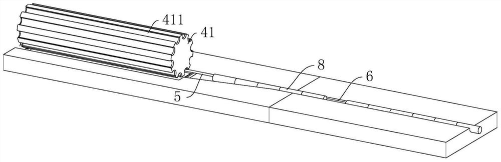
[0039] Embodiment 2: Rod-shaped material transfer device, the difference from Embodiment 1 is that the frame is provided with a transition wheel that is rotated and is used to drive the drive motor 5 that the transition wheel rotates, and the transition wheel is provided with a plurality of transition materials. Groove, the length of the transition trough is set along the axial direction of the transition wheel, and a number of transition troughs are evenly distributed along the circumferential direction of the transition wheel. The transition wheel is equipped with an inner cavity three connected with a negative pressure system and a plurality of air holes three, and the inner cavity three passes through the air holes Three are connected with the transition trough at each place. The transition wheel is located between the feed wheel 1 and the discharge wheel 2, and abuts against the feed wheel 1 and the discharge wheel 2 at the same time.

Embodiment 3

[0040] Embodiment 3: a bar-shaped material transfer device, the difference from Embodiment 2 is that a plurality of transition wheels are provided between the feed wheel 1 and the discharge wheel 2 . The toggle part 4 can also be a cylinder made of other flexible materials.


PUM


Abstract

The invention relates to the field of tobacco production equipment, and discloses a rod-shaped material transfer device, which includes a frame on which a rotating discharge wheel, a synchronous toothed belt, and a driving component are arranged, and a material groove is arranged on the discharge wheel 1. The synchronous toothed belt is provided with shifting teeth; the frame is provided with a blocking surface, which is rotatably connected to the shifting part of the frame. The invention has the following advantages and effects: the axis of the discharge wheel is parallel to the conveying direction of the synchronous toothed belt, and the pulling teeth move the rod-shaped material outside the material groove, without contacting the inner wall of the material groove, reducing the occurrence of failures , to ensure efficient production, the material on the feed wheel is transferred to the discharge wheel, the depth of the material groove 1 on the discharge wheel is smaller than the depth of the material groove 2 on the feed wheel, when the teeth are moved The large contact area with the rod-shaped material is convenient to pull out the rod-shaped material, ensuring the quality of the rod-shaped material during the transfer process, achieving the effect of high transfer efficiency and ensuring the production quality of the rod-shaped material.

Description

technical field [0001] The invention relates to the field of tobacco production equipment, in particular to a rod-shaped material transfer device. Background technique [0002] In tobacco production equipment, the working parts of the filter rod compound machine and other equipment are feeding wheels with negative pressure, and the rod-shaped materials such as filter rods are in rotary motion. When they are transported to other production equipment, their circular motion needs to be converted into a straight line. sports. In the prior art, the circular chain is driven by a driving part, and the chain is provided with teeth, and the teeth are embedded in the material groove of the feed wheel, and the chain forms a certain angle with the axis of the feed wheel, and the teeth on the chain Enter the material groove of the feed wheel to dial out the material. The above method has the following disadvantages: the chain needs to be lubricated during use, and oil stains are easy t...

Claims


Application Information

Patent Timeline
Patent Type & Authority Patents(China)
IPC IPC(8): A24C5/47
CPCA24C5/478
Inventor 杨秋波
Owner XIANGYANG SHENGUAN MECHANICAL & ELECTRICAL TECH CO LTD
Why Eureka
Try Eureka