Laser cosmetic instrument for treating scar

A cosmetology instrument and laser technology, applied in the field of cosmetology equipment, can solve problems such as damage to the normal parts of patients, unstable operation process, poor quality of laser treatment, etc., and achieve complete integrity, stable and convenient installation, and convenient disassembly and movement Effect

Active Publication Date: 2019-11-08
广州中科医疗美容仪器有限公司
View PDF10 Cites 2 Cited by
  • Summary
  • Abstract
  • Description
  • Claims
  • Application Information

AI Technical Summary

Problems solved by technology

However, the manual operation process is unstable and inaccurate, which will damage the normal parts of the patient, and the quality of laser treatment is poor.

Method used


Image

  • Laser cosmetic instrument for treating scar
  • Laser cosmetic instrument for treating scar
  • Laser cosmetic instrument for treating scar

Examples


Embodiment 1

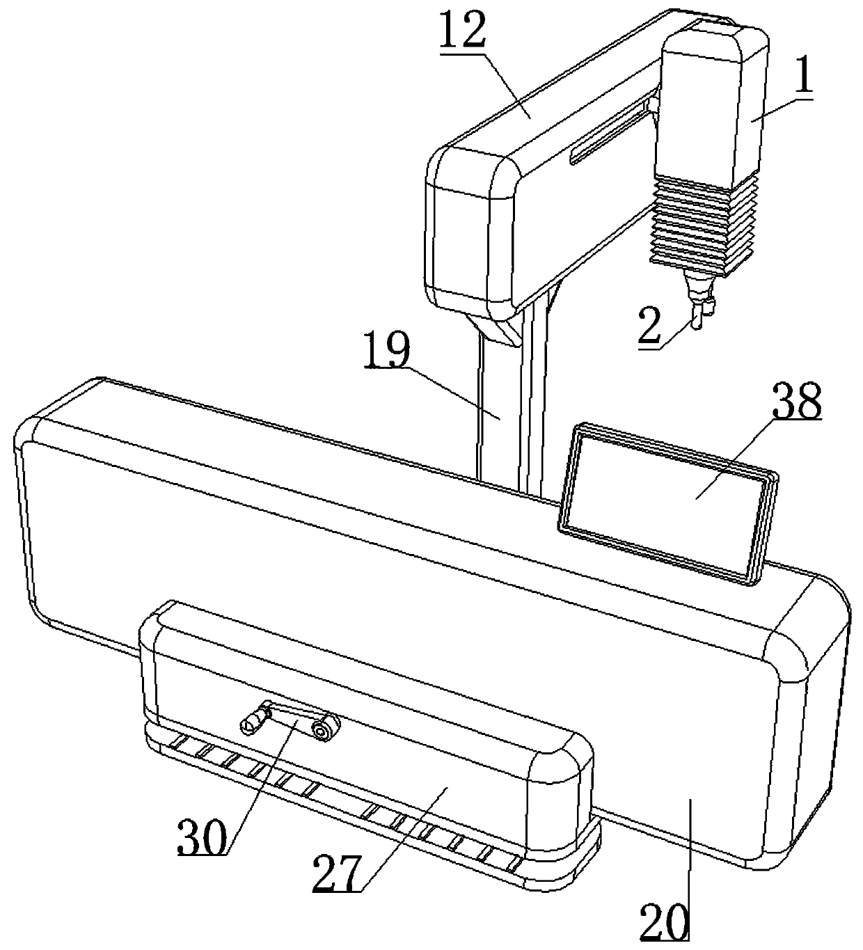
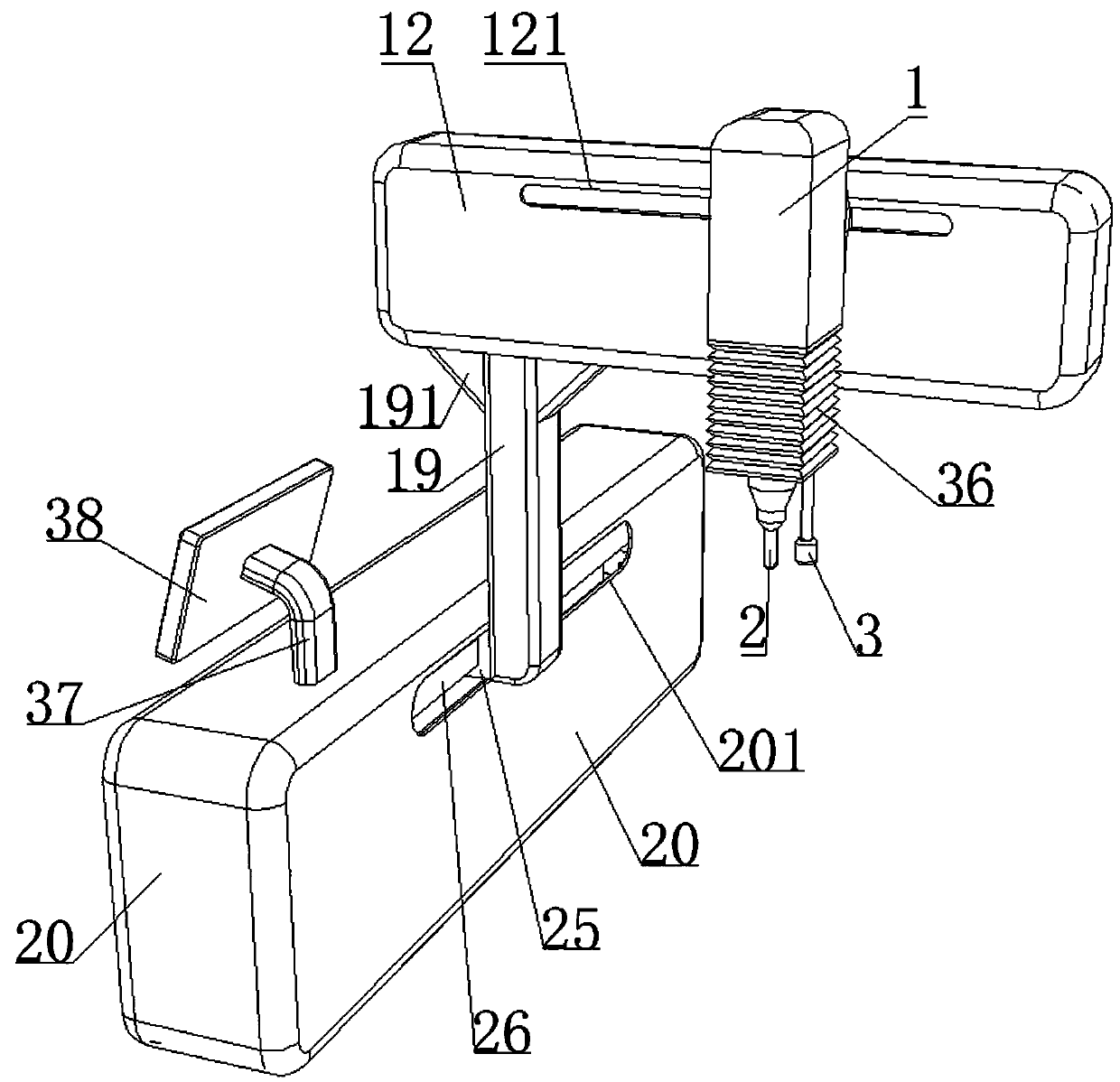
[0034] The main structure of this embodiment, such as Figure 1-7 As shown, it includes a third mounting shell 1, a laser head 2, a mounting plate 4, a second connecting platform 11, a second mounting shell 12, a first connecting platform 19, and a first mounting shell 20;

[0035] The laser head 2 is arranged at the bottom of the mounting plate 4; the mounting plate 4 is arranged at the bottom of the third mounting shell 1; the third mounting shell 1 is provided with a third driving device for driving the mounting plate 4 to move in the vertical direction, the third mounting shell 1 is connected to the second connecting platform 11; the second mounting shell 12 is provided with a second driving device for driving the second connecting platform 11 to move longitudinally, and the second mounting shell 12 is connected to the first connecting platform 19; the first mounting shell A first driving device for driving the first connecting platform 19 to move in the lateral direction is ...

Embodiment 2

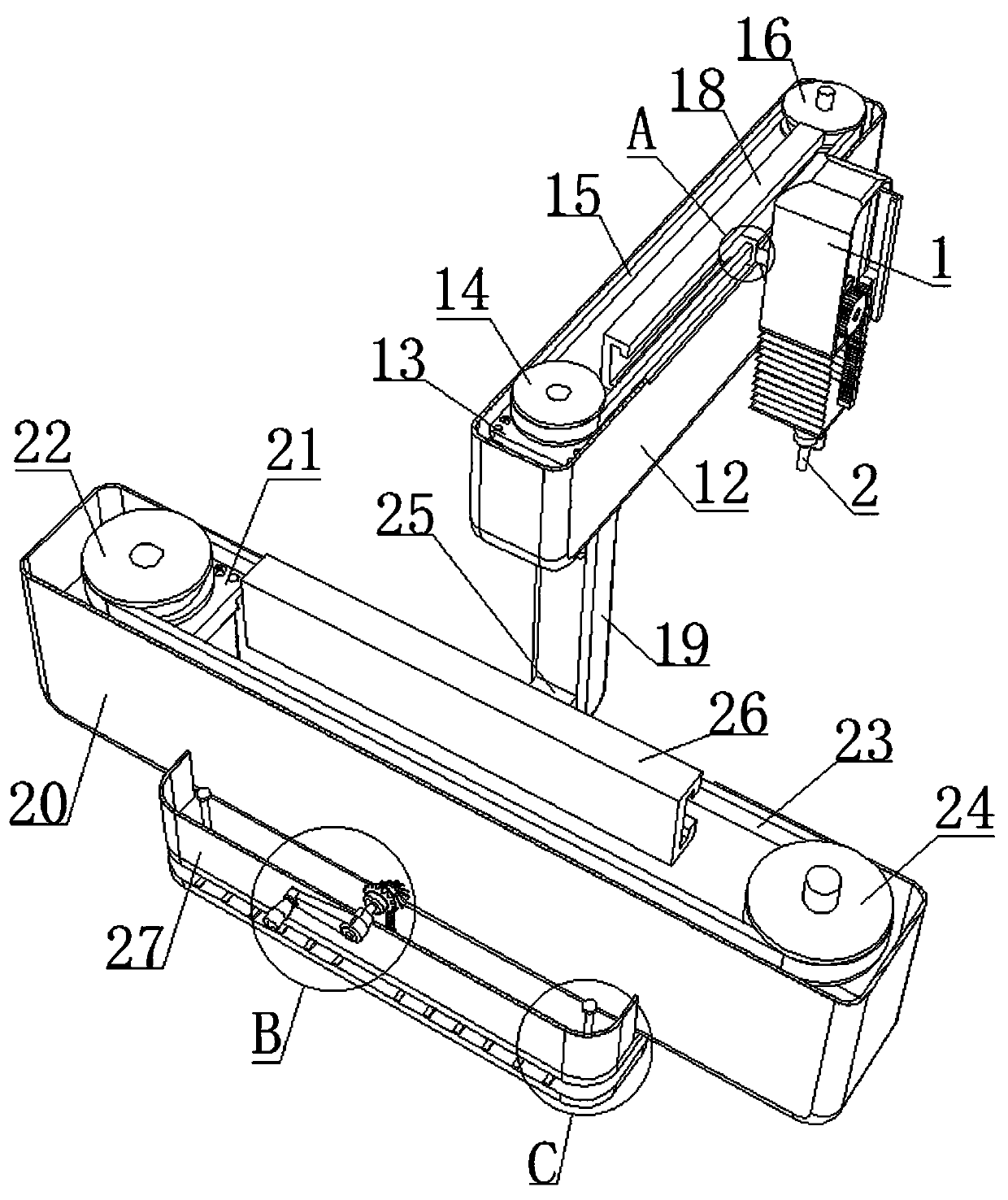
[0050] On the basis of the above embodiments, this embodiment further defines the third driving device, such as Figure 1-7 As shown, the third driving device includes a partition 5, a third driving mechanism 6, a gear 7, a rack 8, a third moving table 9 and a third guiding table 10; the third driving mechanism 6 is arranged on the inner wall of the third mounting shell 1. The gear 7 is in meshing connection with the rack 8; the rack 8 is arranged vertically and connected to the third moving table 9, the rack 8 penetrates the partition plate 5, and the bottom end is connected with the mounting plate 4; The third moving table 9 is connected with the third guiding table 10; the third guiding table 10 is arranged on the inner wall of the third mounting shell 1; the partition plate 5 is arranged on the bottom of the third mounting shell 1, and is located on the mounting plate 4 and the third driving mechanism Between 6.

[0051] It should be noted that the output end of the third dr...

Embodiment 3

[0055] In this embodiment, on the basis of the above embodiment, a clamping assembly is further added, such as Figure 1-7 As shown, the clamping assembly includes a fourth mounting shell 27, a bottom plate 28, a pressing plate 29, a rocking handle 30, a driving bevel gear 31, a driven bevel gear 32, a screw rod 33, a guide rod 34 and a limit platform 35; The handle 30 is connected with the driving bevel gear 31 and is rotatably connected with the fourth mounting shell 27; the driving bevel gear 31 is meshed and connected with the driven bevel gear 32; the driven bevel gear 32 is connected with one end of the screw rod 33; the screw rod 33 is connected with the bottom plate 28 Threaded connection, and the other end is rotatably connected with the pressure plate 29; the guide rod 34 is vertically arranged and penetrates the bottom plate 28, the top end is connected with the limiting platform 35, and the bottom end is connected with the pressure plate 29; the bottom plate 28 is se...


PUM


Abstract

The invention discloses a laser cosmetic instrument for treating scar. The laser cosmetic instrument comprises a third mounting case, a laser head, a mounting plate, a second connecting table, a second mounting case, a first connecting table and a first mounting case, wherein the laser head is arranged at the bottom of the mounting plate; the mounting plate is arranged at the bottom of the third mounting case; a third drive device for driving the mounting plate to move vertically is arranged in the third mounting case, and the third mounting case is connected with the second connecting table;a second drive device for driving the second connecting table to move longitudinally is arranged in the second mounting case, and the second mounting case is connected with the first connecting table;and a first drive device for driving the first connecting table to move transversely is arranged in the first mounting case. The laser head can move in the 3D space, so that the laser head can be stabilized at scar parts of a patient for laser therapy, the condition of inaccuracy of existing cosmetic instruments during manual operation by workers is avoided, and the laser treatment quality of scar is guaranteed.

Description

Technical field [0001] The present invention relates to the technical field of beauty instruments, in particular to a laser beauty instrument for treating scars. Background technique [0002] Modern laser technology has been applied to the treatment field of cosmetic skin science. It is one of the breakthrough developments in the dermatology profession in recent years. In just about ten years, laser technology has formed a relatively complete theoretical system and clinical practice. Practice has become one of the main treatment methods in cosmetic dermatology, which can be used to remove scars. [0003] When using the existing laser beauty instrument for treating scars, the laser head is generally manually operated manually, and the laser head is aimed at the scar of the patient for laser treatment. However, the manual operation process is unstable and inaccurate, which can damage the normal part of the patient, and the laser treatment quality is poor. Summary of the invention ...

Claims


Application Information

Patent Timeline
Patent Type & Authority Applications(China)
IPC IPC(8): A61N5/067
CPCA61N5/0616A61N2005/0642A61N5/067
Inventor 童显权
Owner 广州中科医疗美容仪器有限公司
Why Eureka
Try Eureka