A magnetite beneficiation device

A technology of magnetite and magnetic separation, applied in flotation, magnetic separation, cleaning methods using liquids, etc., can solve the problems of uneven product size and quality, uneven processing surface, and reduced machine life, so as to improve rolling Crushing effect, increasing the contact area, the overall effect of the crushing effect

Active Publication Date: 2021-05-25
山东域潇锆钛矿业股份有限公司
View PDF10 Cites 0 Cited by
  • Summary
  • Abstract
  • Description
  • Claims
  • Application Information

AI Technical Summary

Problems solved by technology

Because magnetite is mostly a granular aggregate; the hardness is 5.5 to 6.5; , it is difficult to completely split the ore into small enough small sizes, and the processing surface is very uneven, which can easily lead to excessive product size and quality; secondly, because of the strong magnetic physical properties of magnetite, the larger the size, the more magnetic The stronger it is, if the conventional contact crushing scheme is directly adopted, it is easy to cause the ore to adsorb or even adhere to the machine equipment and the cutter head, which is not only not conducive to processing, but also easily causes the machine to jam; thirdly, because the magnet Due to the high-hardness physical properties of ore, if the conventional contact crushing scheme is directly used for violent splitting and fragmentation, high-frequency and large quantities of high-kinetic-energy avalanches will be ejected during the processing process, which is extremely harmful to machines and workers. Potential safety hazards, and will greatly reduce the life of the machine
The devices disclosed in the prior art also have defects such as complex structure, various systems, bulky volume, large floor space, and high cost.

Method used


Image

  • A magnetite beneficiation device
  • A magnetite beneficiation device
  • A magnetite beneficiation device

Examples


Embodiment Construction

[0043] The following will clearly and completely describe the technical solutions in the embodiments of the present invention with reference to the accompanying drawings in the embodiments of the present invention. Obviously, the described embodiments are only some, not all, embodiments of the present invention. Based on the embodiments of the present invention, all other embodiments obtained by persons of ordinary skill in the art without making creative efforts belong to the protection scope of the present invention.

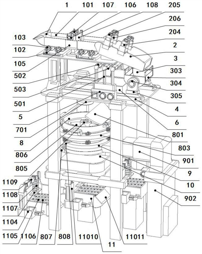
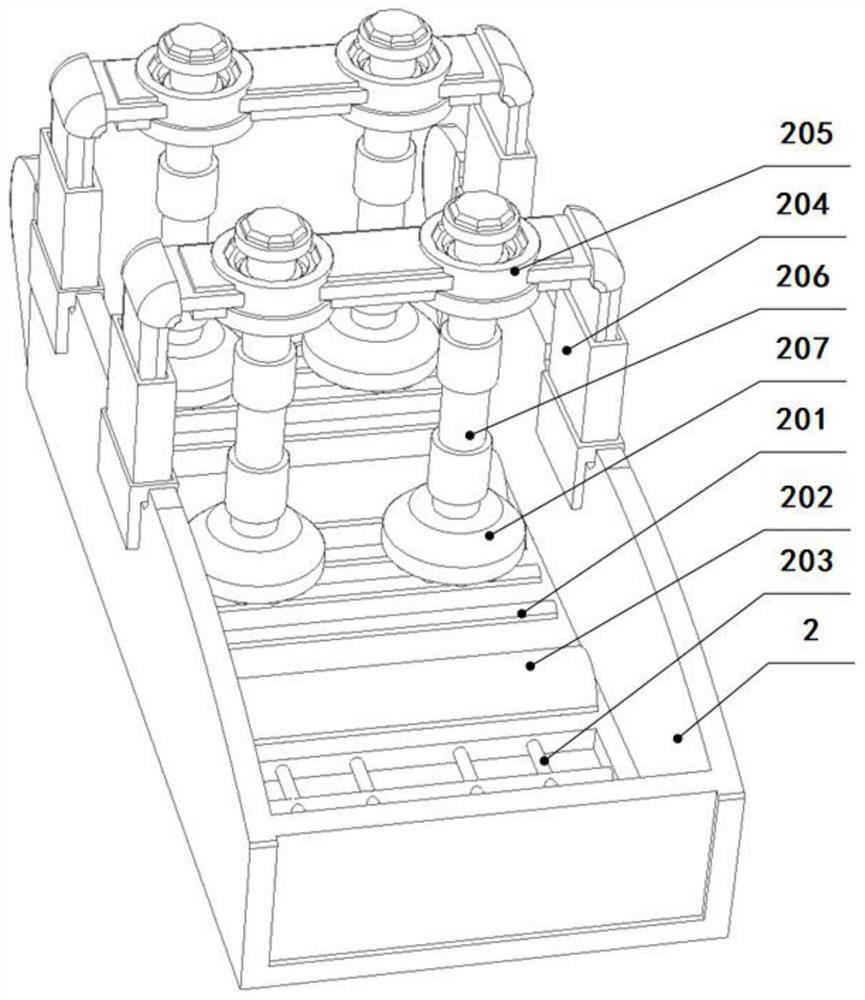
[0044] see Figure 1-12 , a magnetite beneficiation device, including a cutting system, a crushing system, a screening and washing system, a magnetic separation system, and a flotation system arranged in sequence;

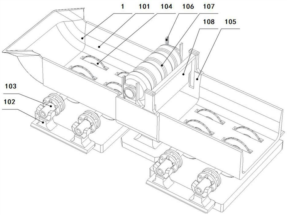
[0045] Described cutting system comprises feeding funnel 1, the working groove one 101 that is connected with feeding funnel 1 lower end, and the working groove two 105 that is arranged on the middle part of working groove one 101, and the bottom o...


PUM

PropertyMeasurementUnit
densityaaaaaaaaaa
hardnessaaaaaaaaaa

Abstract

The invention discloses a magnetite beneficiation device, comprising a cutting system, a crushing system, a screening and washing system, a magnetic separation system, and a flotation system arranged in sequence; the cutting system is divided into two working areas by the working tank two, The cutting mechanisms in the two working areas can respectively cut the upper and lower surfaces of ore raw materials, and the cutting effect is better. The pressure head and convex strip of the crushing mechanism cooperate with rolling and rotating crushing, which can make the upper and lower surfaces of the raw materials have resistance, which can improve the effect of rolling and crushing. The setting of multiple crushing mechanisms can achieve multiple crushing effects. During the rotation of the working chamber of the magnetic separation system, the raw materials follow the rotation and hit each striking rod to achieve the effect of further crushing and dispersion. The evenly dispersed mineral materials are more conducive to the magnetic separation and realize the efficient magnetic suction screening of magnetite collect. The flotation system performs three-stage flotation through three flotation mechanisms, which can effectively improve the effect of flotation and impurity removal, and obtain high-quality magnetite.

Description

technical field [0001] The invention relates to the technical field of mineral processing equipment, in particular to a magnetite mineral processing device. Background technique [0002] The main characteristics of my country's iron ore are "poor", "fine" and "miscellaneous". The iron grade is 32%-37%, which is about 10 percentage points lower than the world average grade. Among them, 97% of the iron ore needs beneficiation, and magnetite ore beneficiation has always been the main body of iron ore beneficiation. Magnetite refers to the ore of the oxide mineral magnetite. Magnetite is mostly a granular aggregate with uneven fracture, hardness 5.5-6.5, density 5.16-5.18g / cm3, and strong magnetism. The ultra-large granular magnetite has extremely high hardness and strong magnetism due to the polymerization effect, while the magnetite with a low degree of compounding has a moderate or small size, low hardness, and is easy to process. [0003] Mineral processing equipment is th...

Claims


Application Information

Patent Timeline
Patent Type & Authority Patents(China)
IPC IPC(8): B02C18/14B02C4/12B02C7/08B02C23/14B02C23/16B08B3/02B03C1/14B03D1/14
CPCB02C4/12B02C7/08B02C18/14B02C23/14B02C23/16B02C2023/165B03C1/14B03D1/14B08B3/02
Inventor 王宗宝
Owner 山东域潇锆钛矿业股份有限公司
Why Eureka
Try Eureka