Numerical control production line of U-rib components for bridge beams

A technology for rib components and bridges, applied in the field of CNC production lines, can solve the problems of manual auxiliary workload, huge equipment investment, unstable quality, etc., achieve the effects of reducing internal stress, improving product quality, and reducing labor

Pending Publication Date: 2019-11-08
红河州新型建筑科技发展有限公司
View PDF0 Cites 1 Cited by
  • Summary
  • Abstract
  • Description
  • Claims
  • Application Information

AI Technical Summary

Problems solved by technology

[0006] The advantage of this production process is that it can produce U-rib components for bridge production that meet the technical requirements, but it has the disadvantages of huge investment in equipment, a large amount of manual auxiliary work, etc. At the same time, high production costs and unstable quality are also problems to be solved.

Method used


Image

  • Numerical control production line of U-rib components for bridge beams
  • Numerical control production line of U-rib components for bridge beams
  • Numerical control production line of U-rib components for bridge beams

Examples


Embodiment Construction

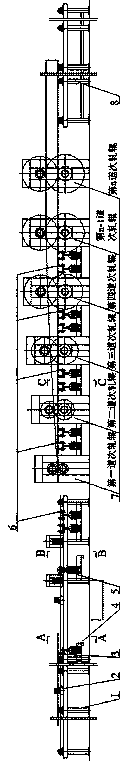
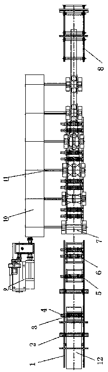
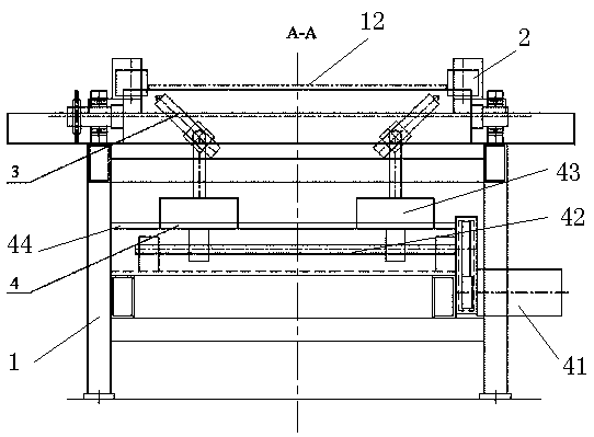
[0032] Such as Figure 1-8 As shown, the feeding and conveying device 1 is composed of a strip-shaped frame, conveying rollers on the frame, and a motor for driving the conveying rollers (the driving motor and corresponding components are omitted in the figure). A conveying roller is set at regular intervals, and when the conveying roller rotates, the steel plate workpiece 12 is conveyed from one end to the other. A pair of vertical positioning nip rollers 2 are arranged at regular intervals on the frame, and the vertical nip rollers are installed on the two slider seats of the centering positioning device 4, and move toward each other to hold (but not clamp dead) the workpiece. Limit the movement of the workpiece to the center of the frame to avoid deviation.

[0033] Bevel cutting torch 3 is installed below the workpiece moving surface in the frame. As mentioned above, the bevel torches are installed in pairs on the two sliding block seats of the centering and positioning ...


PUM


Abstract

The invention provides a numerical control production line of U-rib components for bridge beams. The numerical control production line comprises a feeding conveying device, centering and locating devices, groove cutting guns, pre-heating devices, multi-pass rolling roller units and a discharging conveying device. The multiple centering and locating devices are installed on a rack. Each centering and locating device is formed by a forward and backward screw rod driven by a locating motor and multiple sliding block bases moving on the forward and backward screw rod symmetrically. The groove cutting guns are installed on the centering and locating devices on the feeding conveying device in a pairing manner. Multiple pairs of vertical locating clamping rollers are installed on the respective centering and locating devices. The multi-pass rolling roller units are installed on the rear of the feeding conveying device. The rolling roller unit of each pass is provided with an upper rolling roller and a lower rolling roller. Trapezoidal gaps for workpieces to pass are formed between the upper rolling rollers and the lower rolling rollers. The trapezoidal gaps of the rolling roller units aresequentially closed up along with the advancing direction of the workpieces. The preheating devices are arranged before the rolling roller units. According to the production line, the groove and surface clearing technology and the bent angle bending technology for the U-rib components are combined together for automatic production, the cost is low, the efficiency is high and the quality is excellent.

Description

technical field [0001] The invention relates to a numerically controlled production line for U-rib components used in bridges, belonging to the field of machining equipment. Background technique [0002] The manufacture of steel structure bridges requires the use of many steel U-rib members, which are welded to the bridge deck steel plates to enhance the strength and stiffness of the bridge deck. The shape of the U-rib member used for bridge production is an open isosceles trapezoid, the lower bottom of the trapezoid is open, and the two included angles between the upper bottom and the waist are equal. [0003] The traditional production process of U-rib members is as follows: [0004] 1) Use a special chamfering and milling machine to chamfer one side of the steel plate with the required width and length of the specified steel material; [0005] 2) After the chamfering of the steel plate, two bending machines with hundreds of tons of pressure placed side by side will resp...

Claims


Application Information

Patent Timeline
Patent Type & Authority Applications(China)
IPC IPC(8): B23P23/06
CPCB23P23/06
Inventor 张家云段明红贾宝英张俊春张乔波
Owner 红河州新型建筑科技发展有限公司
Why Eureka
Try Eureka