Automatic clamp for shaft part machining

A shaft part, automatic technology, applied in the aerospace field, can solve the problems of inaccurate positioning of the fixture, low efficiency, grinding and other problems, and achieve the effect of cost saving

Pending Publication Date: 2019-11-08
西安成立航空制造有限公司
View PDF1 Cites 6 Cited by
  • Summary
  • Abstract
  • Description
  • Claims
  • Application Information

AI Technical Summary

Problems solved by technology

[0004] Shaft parts need to be processed in different ways according to the needs before use. The traditional shaft parts clamping method has poor positioning, poor product quality assurance ability during batch processing, and low efficiency. Another example is the above-mentioned Chinese patent CN208163128U, in During processing, it is often necessary to use different fixtures according to different processing parts, and it is also necessary to turn the different faces of the shaft parts to the tool. In this way, when machining shaft parts, the positioning of the fixture will often be inaccurate, and the tool cannot Accurate cutting, grinding, etc. lead to the production of shaft parts that do not meet the requirements. Therefore, this requires an automatic fixture that can fix the shaft parts well and does not need to be re-clamped with different processing parts.

Method used


Image

  • Automatic clamp for shaft part machining
  • Automatic clamp for shaft part machining
  • Automatic clamp for shaft part machining

Examples


Embodiment Construction

[0027] The following will clearly and completely describe the technical solutions in the embodiments of the present invention with reference to the accompanying drawings in the embodiments of the present invention. Obviously, the described embodiments are only some, not all, embodiments of the present invention. Based on the embodiments of the present invention, all other embodiments obtained by persons of ordinary skill in the art without making creative efforts belong to the protection scope of the present invention.

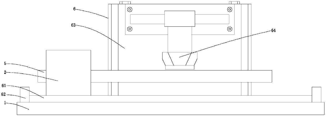
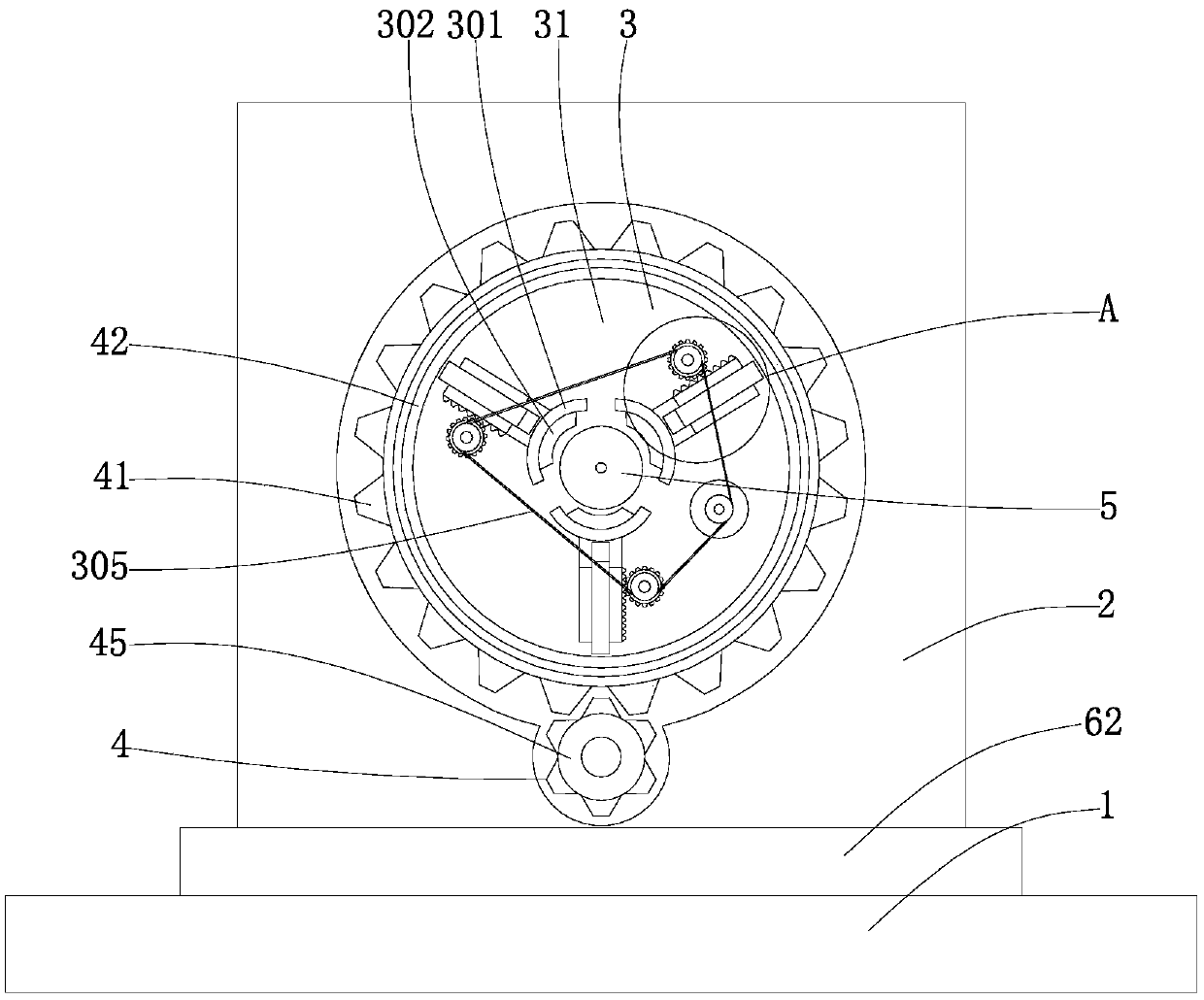
[0028] see Figure 1-5 , the present invention provides a technical solution: an automatic fixture for shaft parts processing, including a base 1, a fixed seat 2, a clamping device 3, a rotating device 4, a shaft part 5 and a moving device 6, and the fixed seat 2 is slidably connected to the On the slide rail 61, the clamping device 3 is fixedly arranged on the first gear 41, the rotating device 4 is fixedly arranged in the fixed seat 2, the shaft parts 5 are ...


PUM


Abstract

The invention discloses an automatic clamp for shaft part machining. The automatic clamp comprises a base, a fixed seat, a clamping device, a rotating device, a shaft part and a moving device. The clamping device comprises a circular table, limiting columns, racks, sliding grooves, second gears, rotating columns, bearings, connecting columns, clamp rings, rubber blankets, first motors, driving wheels, a transmission belt and driven wheels. The circular table is fixedly connected to a first gear. The limiting columns are fixedly connected to the circular table. The racks are in sliding connection to the limiting columns through the sliding grooves. The second gears are fixedly connected to the rotating columns. The connecting columns are fixedly connected to the racks. The clamp rings are fixedly connected to the connecting columns. The first motors are fixedly connected to the circular table. The driving wheels are fixedly connected to the first motors. The transmission belt is connected to the driving wheels. The driven wheels are fixedly connected to the rotating columns. The rotating device comprises a first gear, a locating groove, a locating column, a second motor and a thirdgear. The moving gear comprises a sliding rail, limiting plates, a machining table and a cutter.

Description

technical field [0001] The invention relates to the field of aerospace technology, in particular to an automatic fixture for machining shaft parts. Background technique [0002] In industrial products, shaft parts are suitable for one or more CNC machined part maintenance operations. Shaft parts are one of the typical parts often encountered in hardware accessories. They are mainly used to support transmission parts, transmit torque and bear loads. According to the different structural forms of shaft parts, they can generally be divided into optical shafts, stepped shafts and special-shaped shafts. Three types of shafts; or divided into solid shafts, hollow shafts, etc. [0003] For example, a kind of shaft part drilling jig disclosed in Chinese patent CN208163128U. The drilling jig includes a base for supporting and placing shaft parts to be processed. The base is a stepped structure and is provided with a drilling unit. Mounting holes for machining shaft parts, and dril...

Claims


Application Information

Patent Timeline
Patent Type & Authority Applications(China)
IPC IPC(8): B23Q3/06
CPCB23Q3/064
Inventor 姬宁宁景永平何磊
Owner 西安成立航空制造有限公司
Why Eureka
Try Eureka