Large-span tie bar arch bridge transformation method based on bridge hydraulic jacking system

A large-span, jacking technology, applied in bridges, arch bridges, bridge maintenance and other directions, can solve the problems of difficult to control the jacking construction process, heavy lifting weight, complex process and so on

Active Publication Date: 2019-11-08
NO 1 ENG LIMITED OF CR20G
View PDF6 Cites 1 Cited by
  • Summary
  • Abstract
  • Description
  • Claims
  • Application Information

AI Technical Summary

Problems solved by technology

Among them, when jacking up the main bridge, there are the following construction problems: First, the project is located on the expressway, and the jacking construction must interrupt the traffic, and change the two-way traffic of the double-width bridge to the two-way traffic of the single-width bridge, which will affect the traffic of the expressway Larger, short road closure time, tight construction period, and the necessary closure time during construction is short, so a construction plan that has little impact on navigation must be adopted; second, the jacking weight of the main bridge is huge, and the single jacking weight is 7,000 tons ;Third, during the jacking process, the upper structure of the bridge is in a suspended state, and there are great potential safety hazards, and effective measures must be taken to resolve the above risks to ensure the safety of the bridge and construction personnel; Fourth, the jacking height is relatively high, and the jacking With a height of 2.16m, there are many temporary pads and jacking cycles, which put forward higher requirements for the overall stability of the supporting structure. It is necessary to ensure that the vertical and horizontal support system is firm, reliable and stable.
Correspondingly, when jacking u

Method used


Image

  • Large-span tie bar arch bridge transformation method based on bridge hydraulic jacking system
  • Large-span tie bar arch bridge transformation method based on bridge hydraulic jacking system
  • Large-span tie bar arch bridge transformation method based on bridge hydraulic jacking system

Examples


Embodiment Construction

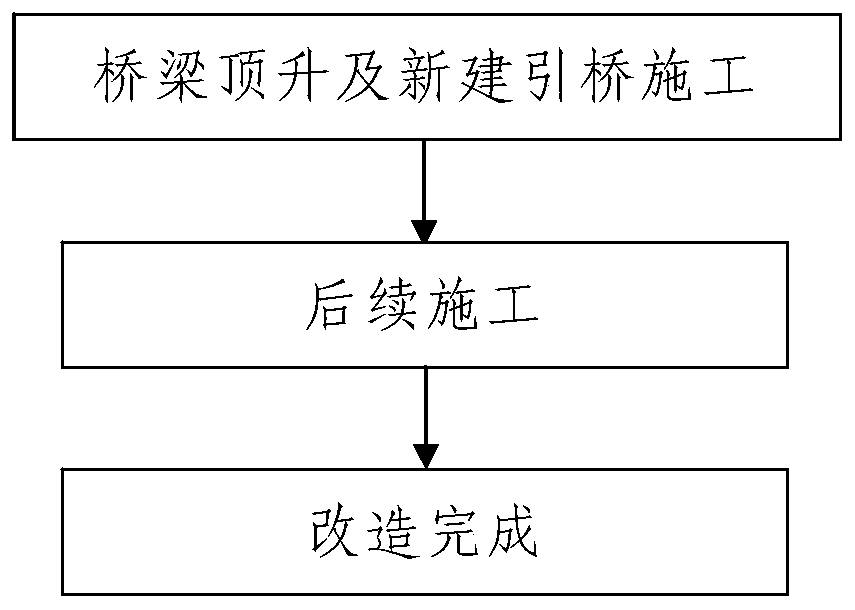
[0194] Such as figure 1 The reconstruction method of the long-span tied-arch bridge based on the hydraulic jacking system of the bridge is shown, the bridge to be reconstructed is a long-span concrete-filled steel pipe tied-arch bridge, and the long-span concrete-filled steel pipe tied-arch bridge includes the main bridge and two connected bridges respectively. In the approach bridges on the front and rear sides of the main bridge, the two approach bridges have the same structure; the two approach bridges are respectively the front approach bridge positioned at the front side of the main bridge and the rear approach bridge positioned at the rear side of the main bridge. The main bridge and the two approach bridges are all arranged on the same vertical plane;

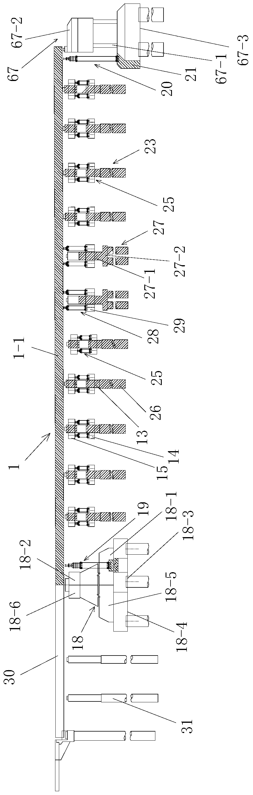
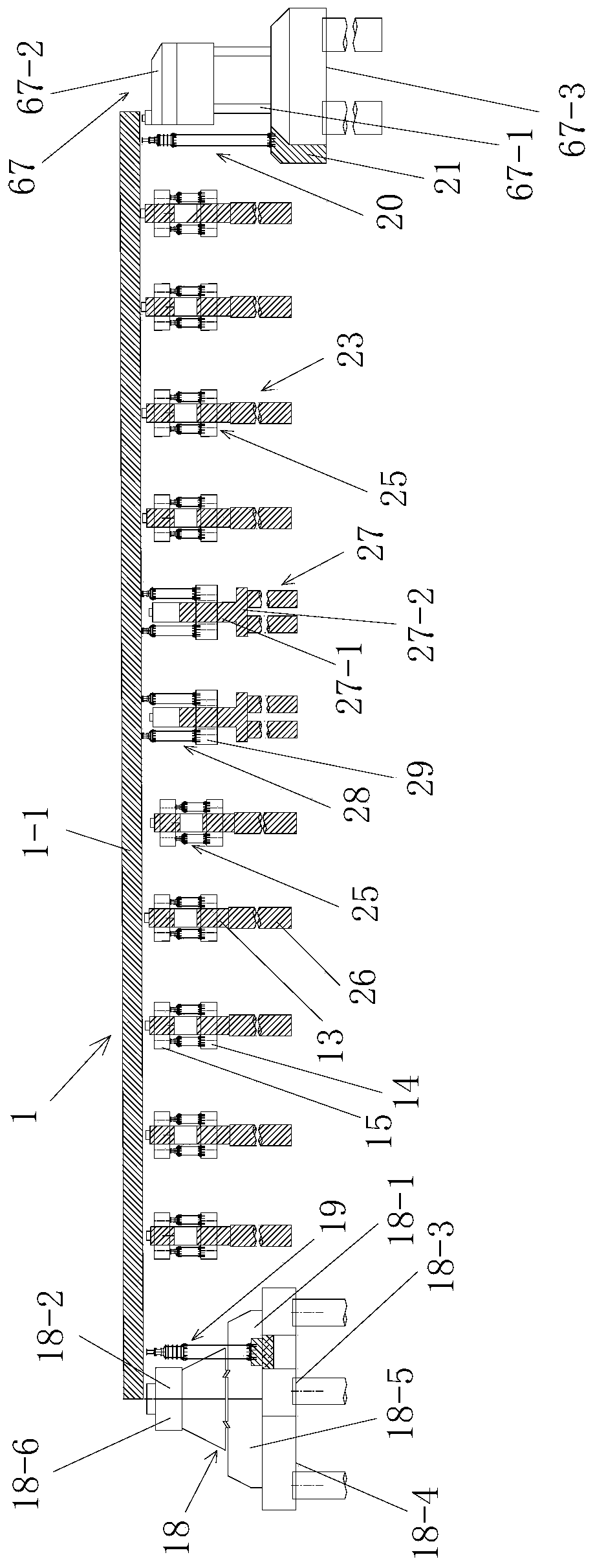
[0195] Such as figure 2 , Figure 22 As shown, the main bridge includes the upper structure of the bridge to be lifted and the lower support structure of the bridge to support the upper structure of the bridge to be l...


PUM


Abstract

The invention discloses a large-span tie bar arch bridge transformation method based on a bridge hydraulic jacking system. A bridge to be transformed comprises a main bridge and two approach bridges.In terms of the transformation of the bridge to be transformed, the transformation method comprises the following steps of 1, carrying out bridge jacking and construction on the newly-built approach bridges, and specifically carrying out jacking construction on a to-be-jacked bridge upper structure of the bridge to be transformed and to-be-jacked approach bridge main beams 1 of the two approach bridges through the bridge hydraulic jacking system; and 2, carrying out subsequent construction. The method has the advantages of being reasonable in design, simple and convenient in construction and good in use effect; jacking for the main bridge and jacking for the two approach bridges are carried out correspondingly, structures and arrangement positions of an approach bridge jacking system and amain bridge jacking system which are adopted are specifically limited, thus being capable of conveniently and rapidly completing the jacking construction process of the large-span arch bridge, and the jacking process is safe and reliable; and in addition, while jacking is carried out on the original bridge upper structure, the two approach bridges on the front and rear portions are newly constructed so that backfilling workload can be effectively reduced, and the construction period can be shortened as well.

Description

technical field [0001] The invention belongs to the technical field of bridge jacking construction, and in particular relates to a reconstruction method for a long-span tied arch bridge based on a bridge hydraulic jacking system. Background technique [0002] Bridge jacking construction (also known as bridge jacking technology) refers to the adoption of the overall hydraulic synchronous lifting scheme, that is, using the original cast-in-place piles to bear the load, without destroying the original bridge deck pavement, railings, sidewalks, and beams and slabs. Connections, etc., first use the hydraulic jacking device to withstand the overall structure of the bridge, then cut off the columns under each pier and platform cap beam, and then operate the hydraulic jacking device to raise the bridge as a whole to the design height, and finally connect the long column steel bars Formwork pouring of the second stage concrete. The bridge superstructure refers to the general term fo...

Claims


Application Information

Patent Timeline
IPC IPC(8): E01D4/00E01D22/00
CPCE01D4/00E01D22/00
Inventor 赵罡颉张记军杜越梁之海李金宝朱书洁汪洋严朝锋王永丽
Owner NO 1 ENG LIMITED OF CR20G
Why Eureka
Try Eureka