I-shaped GFRP-I-shaped steel connector structure, splicing cage for underground diaphragm wall and construction method thereof

An underground diaphragm wall and I-shaped steel technology, which is applied in the direction of foundation structure engineering, excavation, sheet pile walls, etc., can solve problems such as inconvenient construction, high initial risk, and difficult maintenance in the later stage, so as to reduce construction risk and difficulty and speed up construction. Construction progress and the effect of shortening the processing cycle

Pending Publication Date: 2019-11-08
CHINA RAILWAY TUNNEL GROUP CO LTD +1
View PDF0 Cites 4 Cited by
  • Summary
  • Abstract
  • Description
  • Claims
  • Application Information

AI Technical Summary

Problems solved by technology

[0005] The present invention is applicable to the opening door of the shield machine, and provides an I-shaped GFRP-I-shaped steel joint structure, a splicing cage for an underground diaphragm wall and a construction method thereof, so as to solve the problem of the ground connection wall joint in the prior art Technical problems such as poor water-stop effect, high initial risk, and inconvenient follow-up construction
[0006] The present invention is applicable to the connecting wall of the underground shield tunnel line passing through the foundation pit enclosure structure, and provides an I-shaped GFRP-I-shaped steel joint structure, a splicing cage for the underground diaphragm wall and a construction method thereof to solve the problem of Difficulty and high risk of construction, technical problems of difficult later maintenance

Method used


Image

  • I-shaped GFRP-I-shaped steel connector structure, splicing cage for underground diaphragm wall and construction method thereof
  • I-shaped GFRP-I-shaped steel connector structure, splicing cage for underground diaphragm wall and construction method thereof
  • I-shaped GFRP-I-shaped steel connector structure, splicing cage for underground diaphragm wall and construction method thereof

Examples


Embodiment 1

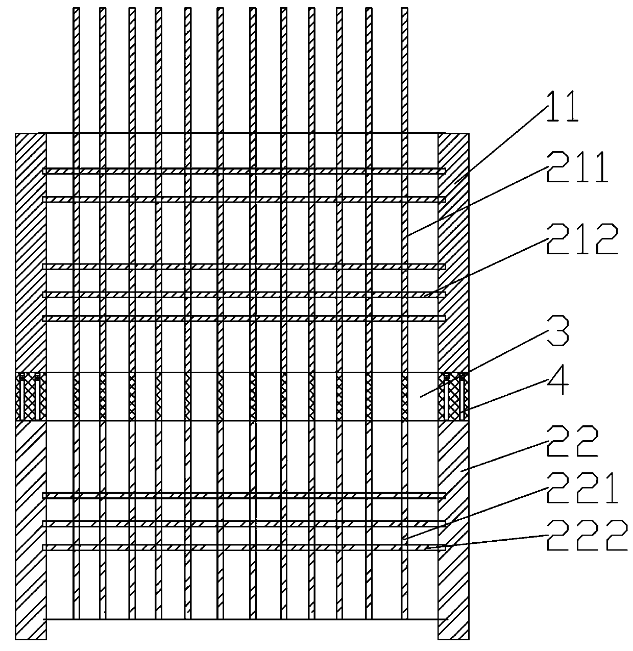
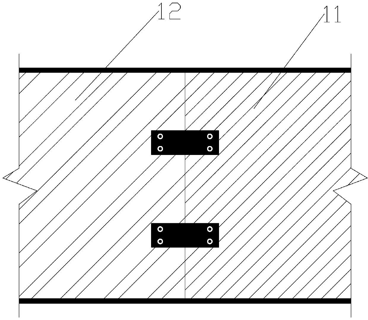
[0036] Embodiment 1: A kind of I-shaped GFRP-I-shaped steel joint structure, see Figure 3-4 , including two spliced ​​I-beams 1, the spliced ​​I-beam 1 includes I-shaped steel 11 and I-shaped GFRP12 seamlessly connected to it through the steel plate 4 and matched in size, wherein the I-shaped steel 11 is welded to the steel plate 4, and the I-shaped steel The type GFRP12 and the steel plate 4 are fixed by punching holes at the corresponding positions of the two and fixing them with screws.

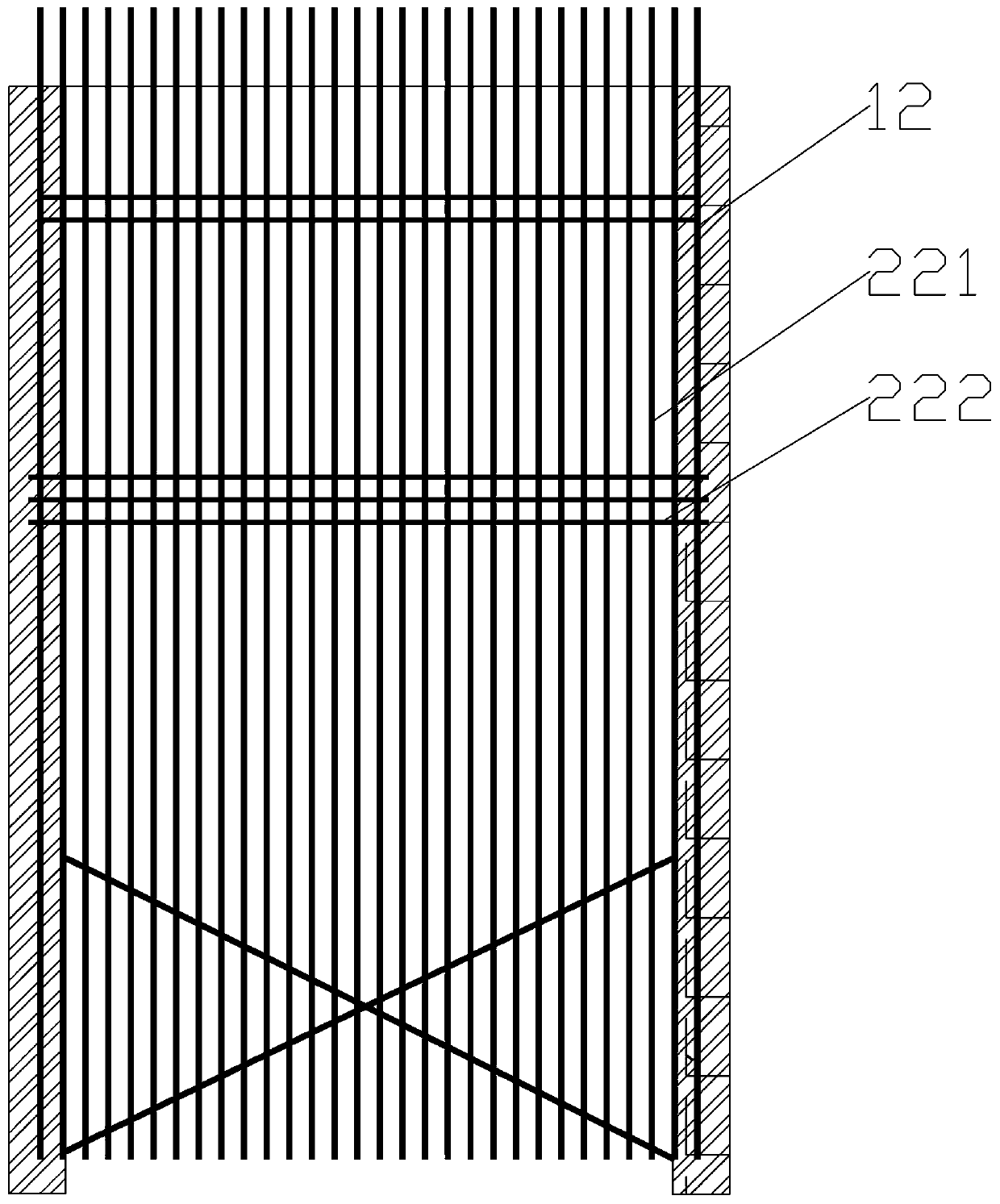
[0037] A splice cage for underground diaphragm walls, see Figure 1-8 The splicing cage includes two above-mentioned splicing I-beams and cage body 2, and the cage body of the I-shaped GFRP12 section is provided with a GFRP reinforcement-steel mixed cage body 22 formed by main reinforcement, distribution reinforcement, truss reinforcement, and scissors reinforcement, wherein the I-shaped The flanges of the GFRP12 section are connected with distribution bars made of 4mm steel wires. The m...


PUM


Abstract

The invention discloses an I-shaped GFRP-I-shaped steel connector structure. The I-shaped GFRP-I-shaped steel connector structure comprises I-shaped steel and I-shaped GFRPs. The I-shaped GFRPs and the I-shaped steel are in seamless connection and are matched in size. The invention further discloses a splicing cage for an underground diaphragm wall. The splicing cage comprises two pieces of spliced I-shaped steel of the I-shaped GFRP-I-shaped steel connector structure. Wing plates of the two pieces of spliced I-shaped steel are connected with main rebars, truss rebars and scissor rebars to form any one of the GFRP cage, the rebar cage and the GFRP-rebar cage, and the main rebars, the truss rebars and the scissor rebars are made of GFRP ribs / rebar materials which are longitudinally and horizontally crossed. The invention further discloses a construction method of the splicing cage for the underground diaphragm wall. The construction method is used for solving the technical problems thatthe water stop effect of the connection portion of the underground diaphragm wall of a starting hole door of a shield tunnelling machine is poor, the starting risk is high, the construction difficulty and the risk degree in the process that an underground shield tunnel line downwards passes through the underground diaphragm wall of a foundation pit enclosure structure are high, and the later-period maintenance is difficult.

Description

technical field [0001] The invention relates to the technical field of foundation pit enclosure structure construction and underground diaphragm wall construction, in particular to an I-shaped GFRP-I-shaped steel joint structure, a splicing cage for an underground diaphragm wall and a construction method thereof. Background technique [0002] With the acceleration of urban rail transit and urban construction, there are more and more infrastructure constructions such as urban subways, high-speed railways, underground stations and underground plazas. As an enclosure structure, underground diaphragm walls have also been widely used in the foundation pit engineering support process. development application. The underground continuous wall is to excavate or punch a trench with a certain width and depth at a predetermined position along the periphery of the underground building or structure through special digging (flushing) equipment, and use mud to protect the wall. A steel cag...

Claims


Application Information

Patent Timeline
IPC IPC(8): E02D5/20E02D17/04E02D19/18
CPCE02D5/20E02D17/04E02D19/185
Inventor 申亚飞谢利阳刘力周勇邢匡宇简凡张辉易大勇韩宛宛吴梁辉张程俊
Owner CHINA RAILWAY TUNNEL GROUP CO LTD
Why Eureka
Try Eureka