Depth information measurement method based on single-frame dense shape coding

A technology of depth information and shape coding, applied in the field of measurement, can solve problems such as inconsistent reflectivity, loss, and long measurement time, and achieve the effects of simplifying the implementation process, avoiding matching failure, and improving accuracy

Inactive Publication Date: 2019-11-08
XIDIAN UNIV
View PDF5 Cites 2 Cited by
  • Summary
  • Abstract
  • Description
  • Claims
  • Application Information

AI Technical Summary

Problems solved by technology

[0005] Spatial coding, which is characterized by only projecting a template, the coding information of each pixel in the template can be obtained in combination with its neighborhood, which is usually suitable for depth acquisition in dynamic scenes, but because the spatial coding may be affected by the neighborhood information during the decoding process Problems such as the loss of the object surface reflectance and the surface color of the object to be measured are likely to cause decoding errors and cause depth information calculation errors. Therefore, the resolution and accuracy of spatial encoding are lower than that of time encoding.
[0006] Time coding, the common ones are binary coding, n-valued coding and mixed coding. Although these coding methods have the advantages of simple and easy to implement, high spatial resolution and high measurement accuracy, but because they need to project multiple measurement templates, the measurement time is relatively long. long and thus only suitable for depth measurements in static scenes

Method used


Image

  • Depth information measurement method based on single-frame dense shape coding
  • Depth information measurement method based on single-frame dense shape coding
  • Depth information measurement method based on single-frame dense shape coding

Examples


Embodiment Construction

[0030] The present invention is an improvement on the traditional structured light method, and does not need to add additional measuring equipment and measuring steps. The present invention will be further described in detail with reference to the accompanying drawings.

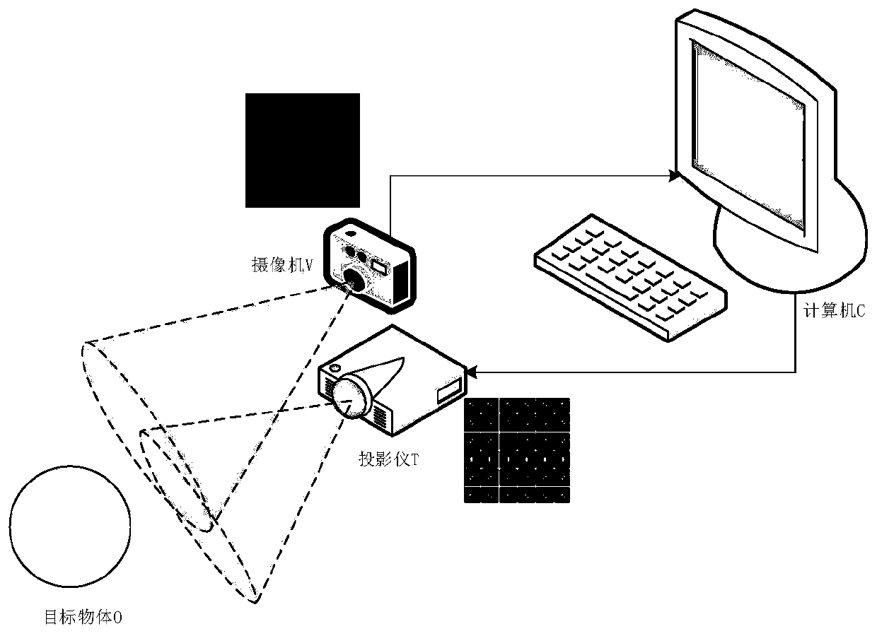
[0031] refer to figure 1 , the depth information acquisition system used in the present invention includes: a target object O to be measured, a camera V, a projector T and a computer C. The projector T projects a single-frame compound grid template P onto the target object O, and the camera V shoots the target to obtain the deformed image I modulated by the target object O.

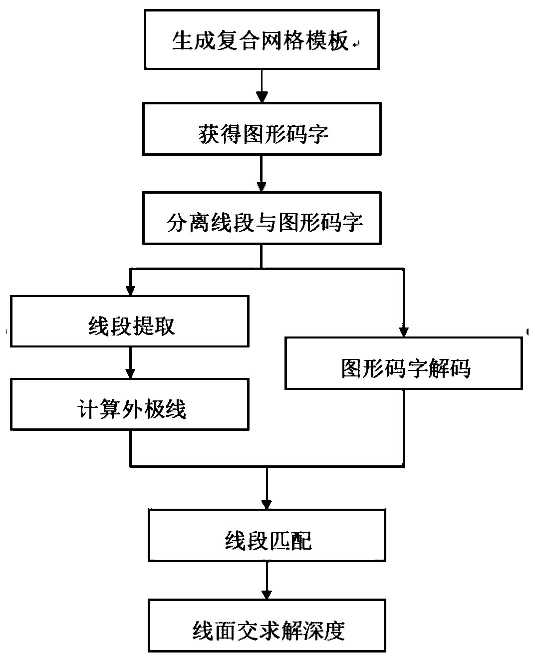
[0032] refer to figure 2 , the present invention is based on the depth information measurement method of single-frame compound network template, and its realization steps are as follows:

[0033] Step 1, design a single-frame composite grid template P.

[0034] (1a) Use 3 kinds of digital symbols to generate the eigenpolynomial h(x) ...


PUM


Abstract

The invention discloses a depth information measurement method based on a single-frame composite network template, and mainly solves the problems that an existing time coding method consumes too longtime, cannot dynamically measure scene depth information and is low in depth information density. According to the scheme, the method comprises steps of designing a single-frame composite network template P; projecting P to a target object, and shooting the target object to obtain a deformed image; transmitting the deformed image to a computer so as to separate a codeword graph I '2 and a line segment grid graph I' 1 from the deformed image; performing line extraction by utilizing the separated line segment grid chart I '1 to obtain a line segment grid chart; decoding according to the separated codeword graph I '2, and solving a line segment matched with the template by decoding the codeword at the intersection point of the horizontal line segment and the vertical line segment; and calculating the depth information value of the to-be-measured object according to the line-plane intersection principle by utilizing the corresponding relation between the line segments. The method can dynamically obtain scene depth information, is high in data precision, and can be used for industrial monitoring, medical science, man-machine interaction, virtual reality and 3D printing.

Description

technical field [0001] The invention belongs to the technical field of measurement, and mainly relates to a method for measuring depth information, which can be applied to industrial monitoring, medical science, human-computer interaction, virtual reality, reality augmentation and 3D printing scenes. Background technique [0002] The signals collected by traditional imaging instruments are only two-dimensional information in the spatial domain, and the depth information in three-dimensional scenes cannot be collected. With the development of computer science and the improvement of people's living standards, two-dimensional information can no longer meet the needs of actual production and life. How to quickly and efficiently obtain 3D depth information from the scene has become a hot topic of current research. [0003] Depth acquisition refers to acquiring depth information of objects in a 3D scene. Currently, depth acquisition methods are mainly divided into active and pas...

Claims


Application Information

Patent Timeline
Patent Type & Authority Applications(China)
IPC IPC(8): G06T7/50
CPCG06T7/50
Inventor 李甫李泉录牛毅石光明蒋景松陶清龙张天娇
Owner XIDIAN UNIV
Why Eureka
Try Eureka