
An anode chamber, method and battery for substantially increasing the power density of MC-DCFC

A power density, anode chamber technology, applied in the field of MC-DCFC, can solve the problems of insufficient contact between carbon powder fuel and electrolyte, easy to float above the molten electrolyte, easy to be oxidized by air, etc., to improve the test efficiency, simple structure, The effect of welding and fixing is convenient

Active Publication Date: 2020-12-08
HUAZHONG UNIV OF SCI & TECH
View PDF26 Cites 0 Cited by
  • Summary
  • Abstract
  • Description
  • Claims
  • Application Information

AI Technical Summary

Problems solved by technology

[0023] Aiming at the above defects or improvement needs of the prior art, the present invention provides an anode chamber that improves the power density of the molten carbonate direct coal / carbon fuel cell, the purpose of which is to enable the carbon powder fuel to be Fully submerged in the molten carbonate electrolyte to ensure a predetermined concentration of carbon slurry, so as to fully contact and react, thereby solving the problem that in the prior art, the carbon powder fuel is easy to float above the molten electrolyte, which leads to insufficient contact between the carbon powder fuel and the electrolyte, and is easily destroyed. Technical problems of air oxidation and reaction rate reduction

Method used


Image

  • An anode chamber, method and battery for substantially increasing the power density of MC-DCFC
  • An anode chamber, method and battery for substantially increasing the power density of MC-DCFC
  • An anode chamber, method and battery for substantially increasing the power density of MC-DCFC

Examples


Embodiment Construction

[0051] In order to make the object, technical solution and advantages of the present invention clearer, the present invention will be further described in detail below in conjunction with the accompanying drawings and embodiments. It should be understood that the specific embodiments described here are only used to explain the present invention, not to limit the present invention. In addition, the technical features involved in the various embodiments of the present invention described below can be combined with each other as long as they do not constitute a conflict with each other.

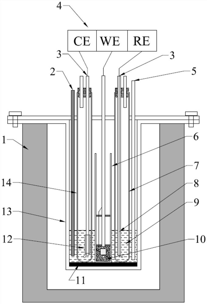
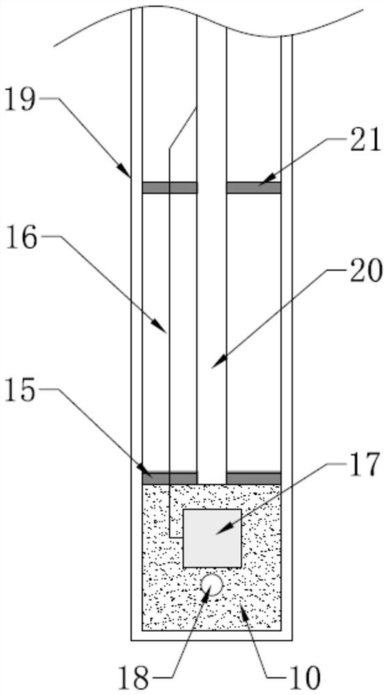
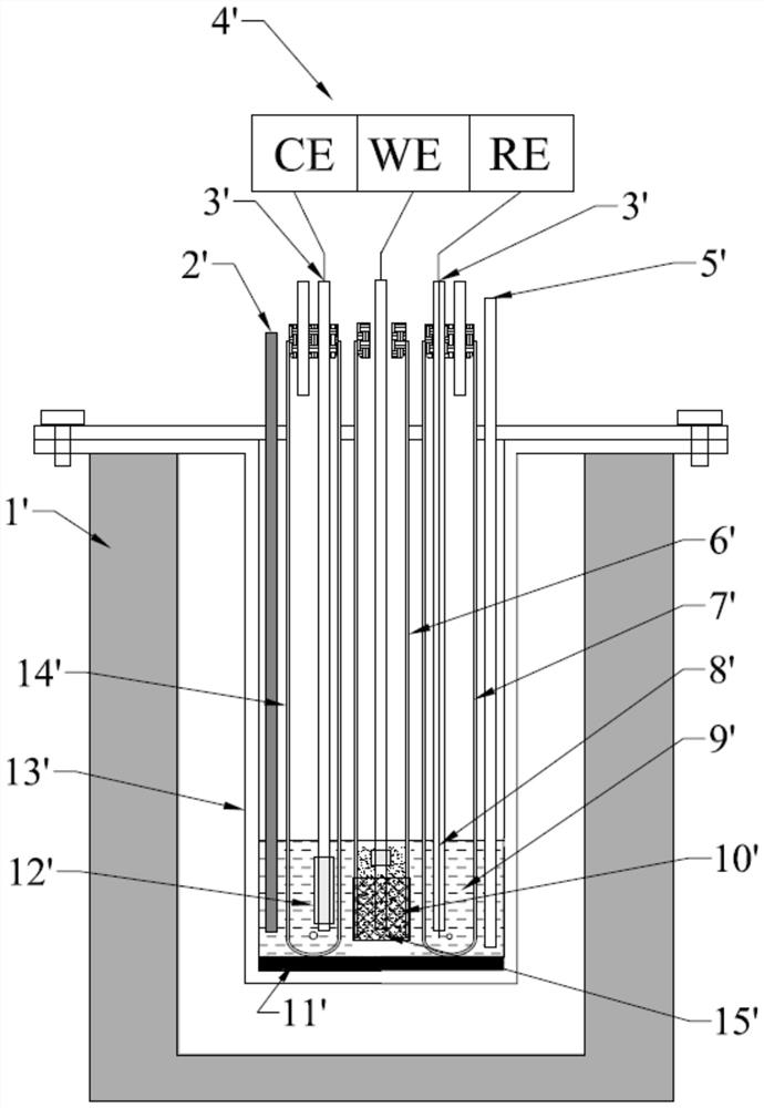
[0052] figure 1 , figure 2 It is a structural schematic diagram of a molten carbonate direct coal / carbon fuel cell and its anode chamber in a preferred embodiment of the present invention. The battery mainly includes: a heating furnace 1 , a battery body 13 , and an anode chamber 6 . The structure of the anode chamber 6 is mainly composed of the following components: 316 stainless steel tube ...


PUM

PropertyMeasurementUnit
particle diameteraaaaaaaaaa
sizeaaaaaaaaaa

Abstract

The invention discloses an anode chamber capable of greatly improving MC-DCFC power density, method and a battery, which belong to the MC-DCFC field. An electrode assembly in the anode chamber can befreely picked and placed in a heat-resistant hard tube, and comprises a pick-and-place rod, a lower limiting plate, a high temperature-resistant insulated wire and a current collector; the lower limiting plate is fixed to the lower end of the pick-and-place rod, and the periphery of the lower limiting plate is matched with the inner wall gap of the heat-resistant hard tube; the current collector is located below the pick-and-place rod; one end of the high temperature-resistant insulated wire is connected with the current collector and the other end passes through a through hole in the lower limiting plate to connect an external device in use; the lower limiting plate and the lower end of the heat-resistant hard tube form space for accommodating fuel powder in a surrounding mode, and the current collector is located in the space; and the lower end of the heat-resistant hard tube is provided with a circulation hole for enabling molten carbonate to flow to the heat-resistant hard tube andbe mixed with the fuel powder in use. Sufficient contact between coal / carbon powder fuel and the molten electrolyte can be ensured, the reaction rate is improved, and the MC-DCFC power density is greatly improved.

Description

technical field [0001] The invention belongs to the field of MC-DCFC (Molten Carbonate direct coal / carbon fuel cell, molten carbonate direct coal / carbon fuel cell), and relates to an anode chamber, method and battery for greatly improving the power density of MC-DCFC, more specifically , relates to an anode chamber design and method for greatly increasing the power density of a molten carbonate direct coal / carbon fuel cell. Background technique [0002] The dominant position of coal in my country's energy will not change for quite a long time. The efficiency of traditional coal-fired power plants is only 30-45%, and they emit a lot of greenhouse gases and pollutants such as SO 2 , NO x , particulate matter, etc. The direct coal / carbon fuel cell (DCFC) directly converts the chemical energy of coal / carbon into electrical energy, nearly doubles the energy conversion efficiency, and greatly reduces energy loss and pollutant emissions; and obtain high-purity CO 2 , easy to s...

Claims


Application Information

Patent Timeline
Patent Type & Authority Patents(China)
IPC IPC(8): H01M8/14
CPCH01M8/14H01M8/143H01M2008/147Y02E60/50
Inventor 傅培舫别康刘洋龚宇森
Owner HUAZHONG UNIV OF SCI & TECH
Learn More