Method for reducing circumferential temperature difference between motor coil and iron core

An iron core circumference and coil technology is applied in the field of reducing the circumferential temperature difference between the motor coil and the iron core. Achieve good and uniform heat dissipation effect, ensure uniform heat dissipation effect, and achieve the effect of uniform circumferential distribution of wind speed

Active Publication Date: 2019-11-08
DONGFANG ELECTRIC MACHINERY
View PDF9 Cites 3 Cited by
  • Summary
  • Abstract
  • Description
  • Claims
  • Application Information

AI Technical Summary

Problems solved by technology

[0010] The existing technologies represented by the above-mentioned patent documents cannot effectively improve the uniformity of the airflow in the circumferential direction due to poor structural design, cannot achieve uniform distribution of the wind speed in the circumferential direction, cannot effectively reduce the circumferential temperature difference of the motor, and are complicated to operate, which is not easy to implement

Method used


Image

  • Method for reducing circumferential temperature difference between motor coil and iron core
  • Method for reducing circumferential temperature difference between motor coil and iron core
  • Method for reducing circumferential temperature difference between motor coil and iron core

Examples


Embodiment 1

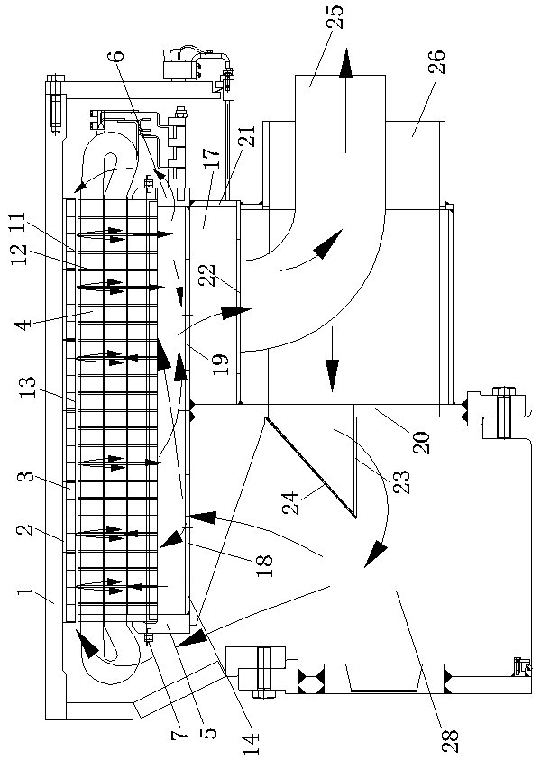
[0037] see Figure 1-Figure 5 , a method for reducing the circumferential temperature difference between a motor coil and an iron core, comprising the following steps:

[0038] a. Install the device for reducing the circumferential temperature difference between the large-diameter motor coil and the iron core on the wind turbine;

[0039] b. Install an oblique windshield 24 at the outlet of the air inlet pipe 26, the angle between the oblique windshield 24 and the first vertical plate 20 is 30°, and install an air volume adjustment plate 27 on the air inlet 18 , the air volume regulating plate 27 is hinged to the first circumferential ring plate 14, and the air circumferential resistance is adjusted through the air volume regulating plate 27;

[0040] c. In a circumferentially symmetrical unit, the wind passage area 29 near the fan axis is the smallest, and the wind passage area 29 at the far fan end away from the fan axis is the largest.

[0041] "a. Install the device to r...

Embodiment 2

[0043] see Figure 1-Figure 5 , a method for reducing the circumferential temperature difference between a motor coil and an iron core, comprising the following steps:

[0044] a. Install the device for reducing the circumferential temperature difference between the large-diameter motor coil and the iron core on the wind turbine;

[0045] b. Install an inclined windshield 24 at the outlet of the air inlet pipe 26, the angle between the inclined windshield 24 and the first vertical plate 20 is 45°, and install an air volume regulating plate 27 on the air inlet 18 , the air volume regulating plate 27 is hinged to the first circumferential ring plate 14, and the air circumferential resistance is adjusted through the air volume regulating plate 27;

[0046] c. In a circumferentially symmetrical unit, the wind passage area 29 near the fan axis is the smallest, and the wind passage area 29 at the far fan end away from the fan axis is the largest.

[0047] The device for reducing t...

Embodiment 3

[0050] see Figure 1-Figure 5 , a method for reducing the circumferential temperature difference between a motor coil and an iron core, comprising the following steps:

[0051] a. Install the device for reducing the circumferential temperature difference between the large-diameter motor coil and the iron core on the wind turbine;

[0052] b. Install an oblique windshield 24 at the outlet of the air inlet pipe 26, the angle between the oblique windshield 24 and the first vertical plate 20 is 60°, and install an air volume adjustment plate 27 on the air inlet 18 , the air volume regulating plate 27 is hinged to the first circumferential ring plate 14, and the air circumferential resistance is adjusted through the air volume regulating plate 27;

[0053] c. In a circumferentially symmetrical unit, the wind passage area 29 near the fan axis is the smallest, and the wind passage area 29 at the far fan end away from the fan axis is the largest.

[0054] The device for reducing the...


PUM


Abstract

The invention discloses a method for reducing the circumferential temperature difference between a motor coil and an iron core, which belongs to the technical field of wind driven generators and is characterized by comprising the following steps: a, installing a device for reducing the circumferential temperature difference between a large-diameter motor coil and an iron core on a wind driven generator; b, mounting an oblique wind shield at an outlet of an air inlet pipe, mounting an air volume adjusting plate on air inlet holes, and adjusting the air circumferential resistance through the airvolume adjusting plate; and c, enabling an air passing area of a near fan end close to the axis of the fan to be minimum and an air passing area of a far fan end far away from the axis of the fan tobe the maximum in one circumferential symmetric unit. The method is easy and flexible to operate and convenient to implement, and the airflow circumferential uniformity can be improved; the areas of different air inlet holes can be adjusted by adjusting the sizes of the air inlet holes shielded by the air volume adjusting plate according to actual needs so as to achieve uniform distribution of airspeed in the circumferential direction, and the circumferential temperature difference of the motor can be reduced by 10-20 K.

Description

technical field [0001] The invention relates to the technical field of wind power generators, in particular to a method for reducing the circumferential temperature difference between a motor coil and an iron core. Background technique [0002] For low-speed large-scale rotating motors, especially direct-drive wind turbines, the speed is only about 10r / min, and the pressure generated by the rotating parts is only a few Pa, which cannot drive enough air to flow inside the motor to take away the losses generated during the operation of the motor. The commonly used solution for this kind of motor is to arrange a special fan on the motor base as the main pressure source of air flow, but due to the needs of brakes, locks, outlet boxes, manholes, etc. Usually, the air inlet and outlet of the motor fan can only be arranged at the upper part of the frame. Calculations and tests have shown that this arrangement will cause uneven temperature distribution in the stator coil and iron co...

Claims


Application Information

Patent Timeline
Patent Type & Authority Applications(China)
IPC IPC(8): H02K5/20H02K1/20H02K1/32
CPCH02K1/20H02K1/32H02K5/20
Inventor 王超周光厚蒋小平廖毅刚王峰军杨燕
Owner DONGFANG ELECTRIC MACHINERY
Why Eureka
Try Eureka