A device capable of reducing the circumferential temperature difference between the large-diameter motor coil and the iron core

A technology with iron core circumference and large diameter, applied in electromechanical devices, cooling/ventilation devices, electrical components, etc., can solve the problem that the circumferential uniformity of airflow cannot be effectively improved, the circumferential temperature difference of the motor cannot be effectively reduced, and the circumferential uniformity of wind speed cannot be achieved. distribution and other issues, to ensure the uniformity of heat dissipation, improve the heat dissipation effect, and be easy to process and manufacture.

Active Publication Date: 2020-11-20
DONGFANG ELECTRIC MACHINERY
View PDF8 Cites 0 Cited by
  • Summary
  • Abstract
  • Description
  • Claims
  • Application Information

AI Technical Summary

Problems solved by technology

[0010] The existing technologies represented by the above-mentioned patent documents cannot effectively improve the circumferential uniformity of the airflow due to poor structural design, cannot achieve uniform distribution of wind speed in the circumferential direction, and cannot effectively reduce the circumferential temperature difference of the motor

Method used


Image

  • A device capable of reducing the circumferential temperature difference between the large-diameter motor coil and the iron core
  • A device capable of reducing the circumferential temperature difference between the large-diameter motor coil and the iron core
  • A device capable of reducing the circumferential temperature difference between the large-diameter motor coil and the iron core

Examples


Embodiment 1

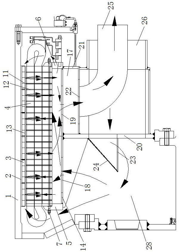
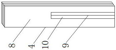
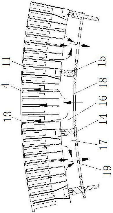
[0034] see Figure 1-Figure 5 , a device for reducing the circumferential temperature difference between a large-diameter motor coil and an iron core, comprising a rotor frame 1, a rotor core 2 mounted on the rotor frame 1, and a plurality of rotor magnets 3 arranged axially along the rotor core 2, It also includes a multi-stage stator core section 4, a first iron core pressing plate 5, a second iron core pressing plate 6, and a tension screw 7. The stator iron core section 4 is formed by stacking silicon steel sheets 8, and the silicon steel sheets 8 are provided with holes for placing In the slot body 10 of the stator coil 9, a stator channel steel 11 is connected between any two adjacent stator core segments 4, and the two stator core segments 4 and the stator channel steel 11 form a stator ventilation groove for cooling medium circulation 12. The tightening screw 7 runs through the multi-stage stator core segment 4, one end of the tightening screw 7 is fixedly connected to...

Embodiment 2

[0037] see Figure 1-Figure 5 , a device for reducing the circumferential temperature difference between a large-diameter motor coil and an iron core, comprising a rotor frame 1, a rotor core 2 mounted on the rotor frame 1, and a plurality of rotor magnets 3 arranged axially along the rotor core 2, It also includes a multi-stage stator core section 4, a first iron core pressing plate 5, a second iron core pressing plate 6, and a tension screw 7. The stator iron core section 4 is formed by stacking silicon steel sheets 8, and the silicon steel sheets 8 are provided with holes for placing In the slot body 10 of the stator coil 9, a stator channel steel 11 is connected between any two adjacent stator core segments 4, and the two stator core segments 4 and the stator channel steel 11 form a stator ventilation groove for cooling medium circulation 12. The tightening screw 7 runs through the multi-stage stator core segment 4, one end of the tightening screw 7 is fixedly connected to...

Embodiment 3

[0044] see Figure 1-Figure 5 , a device for reducing the circumferential temperature difference between a large-diameter motor coil and an iron core, comprising a rotor frame 1, a rotor core 2 mounted on the rotor frame 1, and a plurality of rotor magnets 3 arranged axially along the rotor core 2, It also includes a multi-stage stator core section 4, a first iron core pressing plate 5, a second iron core pressing plate 6, and a tension screw 7. The stator iron core section 4 is formed by stacking silicon steel sheets 8, and the silicon steel sheets 8 are provided with holes for placing In the slot body 10 of the stator coil 9, a stator channel steel 11 is connected between any two adjacent stator core segments 4, and the two stator core segments 4 and the stator channel steel 11 form a stator ventilation groove for cooling medium circulation 12. The tightening screw 7 runs through the multi-stage stator core segment 4, one end of the tightening screw 7 is fixedly connected to...


PUM


Abstract

The invention discloses a device capable of reducing the circumferential temperature difference between a large-diameter motor coil and an iron core, which belongs to the field of wind power generators and includes a rotor base, a rotor iron core and a rotor magnetic steel, and is characterized in that it also includes a multi-section stator iron core section, a first The first iron core pressing plate, the second iron core pressing plate and the tension screw, the stator core section is made of silicon steel sheets stacked, the silicon steel sheet has grooves, the first circumferential ring plate is fixed on the multi-section stator core section, the first circumferential ring At least three axial vertical plates are fixed on the inner wall of the plate, a first vertical plate and a second vertical plate are fixed on the outer wall of the first circumferential ring plate, and a second vertical plate is fixed between the first vertical plate and the second vertical plate. The circumferential ring plate and the first vertical plate are connected to an oblique windshield through a plurality of connecting plates, and an air volume regulating plate is arranged on the air inlet hole. The invention can improve the uniformity of the air flow in the circumferential direction; the area of ​​different air inlet holes can be adjusted to realize the uniform distribution of the wind speed in the circumferential direction, and can reduce the circumferential temperature difference of the motor.

Description

technical field [0001] The invention relates to the technical field of wind power generators, in particular to a device for reducing the circumferential temperature difference between a large-diameter motor coil and an iron core. Background technique [0002] For low-speed large-scale rotating motors, especially direct-drive wind turbines, the speed is only about 10r / min, and the pressure generated by the rotating parts is only a few Pa, which cannot drive enough air to flow inside the motor to take away the losses generated during the operation of the motor. The commonly used solution for this kind of motor is to arrange a special fan on the motor base as the main pressure source of air flow, but due to the needs of brakes, locks, outlet boxes, manholes, etc. Usually, the air inlet and outlet of the motor fan can only be arranged at the upper part of the frame. Calculations and tests have shown that this arrangement will cause uneven temperature distribution in the stator c...

Claims


Application Information

Patent Timeline
Patent Type & Authority Patents(China)
IPC IPC(8): H02K5/20H02K1/20H02K1/32
CPCH02K5/20H02K1/20H02K1/32H02K5/207H02K9/04H02K7/1838H02K2213/09
Inventor 王超周光厚蒋小平廖毅刚王峰军杨燕
Owner DONGFANG ELECTRIC MACHINERY
Why Eureka
Try Eureka