
Dual-12-pulse dual-flow brushless generator

A technology of alternating current generator and direct current generator, applied in the direction of synchronous generator, synchronous machine, electrical components, etc., can solve the problem that the alternating current power supply and the direct current power supply cannot be used at the same time, the output voltage of the direct current power supply is not automatically adjusted, and the DC part voltage ripple Large and other problems, to achieve the effect of flexible power supply characteristics, shortening the length of the motor, and no interference of the excitation source

Pending Publication Date: 2019-11-08
山东德欣电机有限公司
View PDF0 Cites 3 Cited by
  • Summary
  • Abstract
  • Description
  • Claims
  • Application Information

AI Technical Summary

Problems solved by technology

This AC and DC power supply method has the following disadvantages. The output voltage of the DC power supply has no automatic adjustment function, and there is only a fixed DC voltage level, and the ripple of the DC part voltage is relatively large. The AC power supply and the DC power supply cannot be used at the same time. Not suitable for working conditions where AC and DC need to be powered at the same time
[0003] The other is a dual-flow brushless generator with two AC exciters, this generator includes an AC main generator and a DC main generator, the AC main generator is equipped with an exciter, and the DC main generator is configured An exciter, and it is a generator with a number of poles, although it can realize AC and DC separate power supply, but it has a complex structure and great interference of the excitation source

Method used


Image

  • Dual-12-pulse dual-flow brushless generator
  • Dual-12-pulse dual-flow brushless generator
  • Dual-12-pulse dual-flow brushless generator

Examples


Embodiment Construction

[0027] Below in conjunction with accompanying drawing, the present invention is further described:

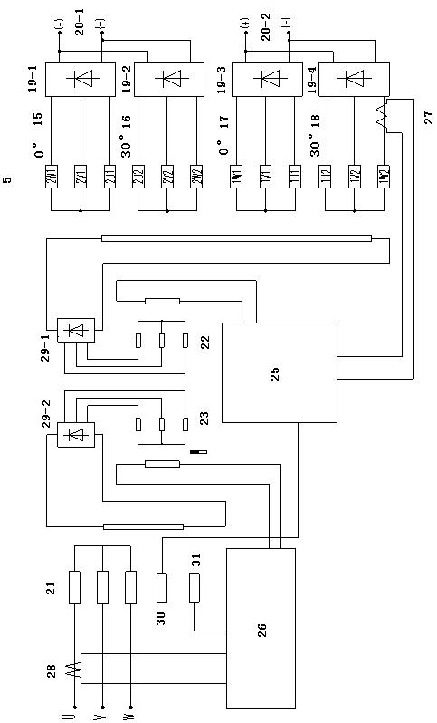
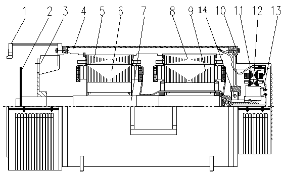
[0028]As shown in the attached figure, a double 12-pulse dual-flow brushless generator mainly includes a base 4, a DC generator stator 5, a DC generator rotor 6, a rotating shaft 7, an AC generator stator 8, and an AC generator rotor 9 , the end cover 10, the exciter stator 11, the exciter rotor 12, the bearing 14, the first rectifier 19-1, the second rectifier 19-2 and the control system, characterized in that the rotating shaft 7 in the cavity of the base 4 is composed of The DC generator rotor 6, the AC generator rotor 9, the bearing 14 and the exciter rotor 12 are fixedly installed in sequence from front to back, so that the DC generator rotor 6, the AC generator rotor 9 and the exciter rotor 12 share a rotating shaft 7 to rotate , the inner wall of the base 4 is fixed with a DC generator stator 5, an AC generator stator 8, an end cover 10 and an exciter stator 11 from fron...


PUM


Abstract

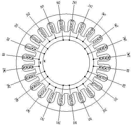
The invention discloses a dual-12-pulse dual-flow brushless generator. The dual-12-pulse dual-flow brushless generator mainly comprises a base, a DC generator stator, a DC generator rotor, a rotatingshaft, an alternating-current generator stator, an alternating-current generator rotor, an end cover, an exciter stator, an exciter rotor, a bearing, a rotary rectifier and the control system. The DCgenerator rotor, the alternating-current generator rotor, the bearing and the exciter rotor are fixedly installed on the rotating shaft in the base cavity in order from front to back, the DC generatorstator, the alternating-current generator stator, the end cover and the exciter stator are fixedly arranged in the base in order from front to back, the groove of the inner circle of the DC generatorstator is internally uniformly embedded with 4 sets of 3-phase windings, wherein the phase angles of the two sets of windings are 0-degree electric angle, the phase angles of the other two sets of windings are 30-degree electric angle, and the four sets of windings are output and then form four sets of direct currents through the rectifier to output. The dual-12-pulse dual-flow brushless generator is simple in structure and flexible in power supply feature, and has no interference of an excitation source and stable performances.

Description

technical field [0001] The invention relates to the field of production and manufacture of special motors, and specifically provides a double-12-pulse double-flow brushless generator. Background technique [0002] At present, there are two main modes of AC and DC power supply for aircraft ground power vehicles: one is to generate AC power from a three-phase AC generator driven by an internal combustion engine, and the DC power is to rectify the above-mentioned AC power through a transformer step-down , forming a DC power supply. This AC and DC power supply method has the following disadvantages. The output voltage of the DC power supply has no automatic adjustment function, and there is only a fixed DC voltage level, and the ripple of the DC part voltage is relatively large. The AC power supply and the DC power supply cannot be used at the same time. It is not suitable for working conditions where both AC and DC power supply are required at the same time. [0003] The othe...

Claims


Application Information

Patent Timeline
Patent Type & Authority Applications(China)
IPC IPC(8): H02K16/00H02K19/38H02K19/36H02K3/16H02K9/06
CPCH02K3/16H02K9/06H02K16/00H02K19/36H02K19/365H02K19/38H02K2213/03
Inventor 郑飞
Owner 山东德欣电机有限公司
Learn More