
Internet of Things visual optimization monitoring equipment

A technology of monitoring equipment and the Internet of Things, which is applied in the direction of TV, color TV, closed-circuit television system, etc., can solve problems such as dust contamination, tilting of the monitor body, and the monitoring range does not match the area, and achieves good cleanliness, high degree of automation, Good dust removal effect

Pending Publication Date: 2019-11-08
福州市协成智慧科技有限公司
View PDF1 Cites 1 Cited by
  • Summary
  • Abstract
  • Description
  • Claims
  • Application Information

AI Technical Summary

Problems solved by technology

[0004] However, such a technical solution still has defects in actual operation. For example, this product is used as a monitoring and warning device in an underground mine. The guide rail does not always extend horizontally, but there is an inclination according to the actual terrain. Due to the influence of its own weight, the sensor will have a certain displacement, so there is a deviation from the predetermined observation position
On the other hand, the environment of underground mines is poor, there will be sand and dust on the slide rails
These clods will cause the monitor body to tilt as it slides over
These will make the monitoring range and area inconsistent with the predetermined
[0005] In addition, the camera is often installed behind the transparent casing of the monitor. As mentioned above, in some bad monitoring environments, dust, etc. will be contaminated on the transparent casing, thereby affecting the shooting quality
In mines, there is often a certain height from the ground, and the cleaning of the camera needs to be done manually, which is extremely inconvenient

Method used


Image

  • Internet of Things visual optimization monitoring equipment
  • Internet of Things visual optimization monitoring equipment
  • Internet of Things visual optimization monitoring equipment

Examples


Embodiment 1

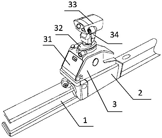
[0043] Example 1, such as figure 1 As shown, the guide rail 1 is included, and the slider 2 slides on the guide rail 1. The driving mode for driving the slide block 2 to slide relative to the guide rail 1 is not limited, and may be a cylinder or a motor-driven rack and pinion in the prior art. The camera assembly 3 is installed on the slider 2, and the two can be fixedly connected. The camera assembly 3 includes a main body 31 , and most electronic components such as chips can be installed in the cavity of the main body 31 . An infrared camera device 33 and a speaker 34 are installed on the rotating table 32, so that the infrared camera device 33 and the speaker 34 can rotate in the horizontal direction and adjust the direction.

[0044] The data communication between the camera assembly 3 and the control system can be transmitted through wireless methods such as Bluetooth, OPM, WIFI, etc., and the specific communication technology is not limited in this case.

[0045] like...


PUM


Abstract

The invention relates to the field of infrared monitoring equipment, in particular to Internet of Things visual optimization monitoring equipment. According to the technical scheme, the Internet of Things visual optimization monitoring equipment comprises a guide rail, a sliding block sliding on the guide rail and a camera shooting assembly installed on the sliding block, the camera shooting assembly comprises a main body, and a real-time infrared camera shooting device comprises a transparent shell. The Internet of Things visual optimization monitoring equipment comprises a camera shooting purification device used for cleaning a transparent shell, and the camera shooting purification device comprises an upper connecting base, a wiping lifting strip connected with the upper connecting baseand a wiping soft block driven by the wiping lifting strip to reciprocate to wipe the surface of the transparent shell. The invention aims to provide Internet of Things visual optimization monitoringequipment, which can move and adjust the monitoring range in real time, clean a transparent shell outside a camera and optimize a shot picture in real time.

Description

technical field [0001] The invention relates to the field of infrared monitoring equipment, in particular to an Internet of Things visual optimization monitoring equipment. Background technique [0002] With the development of information technology and the maturity of Internet of Things technology, security equipment has been more widely used. Due to different sensing methods, security equipment includes visual capture, temperature sensing, odor sensing, physical touch and other categories. Among them, because infrared rays have the characteristics of sensing heat sources, they can be used in dark nights, indoor warehouses, and underground mines with poor visual conditions. It still has good perception and detection performance, and security monitoring and alarm equipment based on infrared technology has also been widely used. [0003] In order to further expand the flexibility of the alarm equipment and the adjustability of the detection range, a movable infrared monitori...

Claims


Application Information

Patent Timeline
IPC IPC(8): H04N7/18H04N5/232B08B1/00B08B5/02
CPCH04N7/183B08B5/02H04N23/695B08B1/143
Inventor 方世玲林存锈林雯炳柯培阳范泰昌
Owner 福州市协成智慧科技有限公司
Learn More