A high-efficiency heat dissipation device for electronic components
A technology for electronic components and heat dissipation devices, applied in the field of efficient heat dissipation devices for electronic components, can solve the problems of insufficient heat dissipation, affecting installation, and increasing the thickness of circuit boards, so as to increase flexibility, reduce installation difficulty, and reduce thickness. Effect
- Summary
- Abstract
- Description
- Claims
- Application Information
AI Technical Summary
Problems solved by technology
Method used
Image
Examples
Embodiment 1
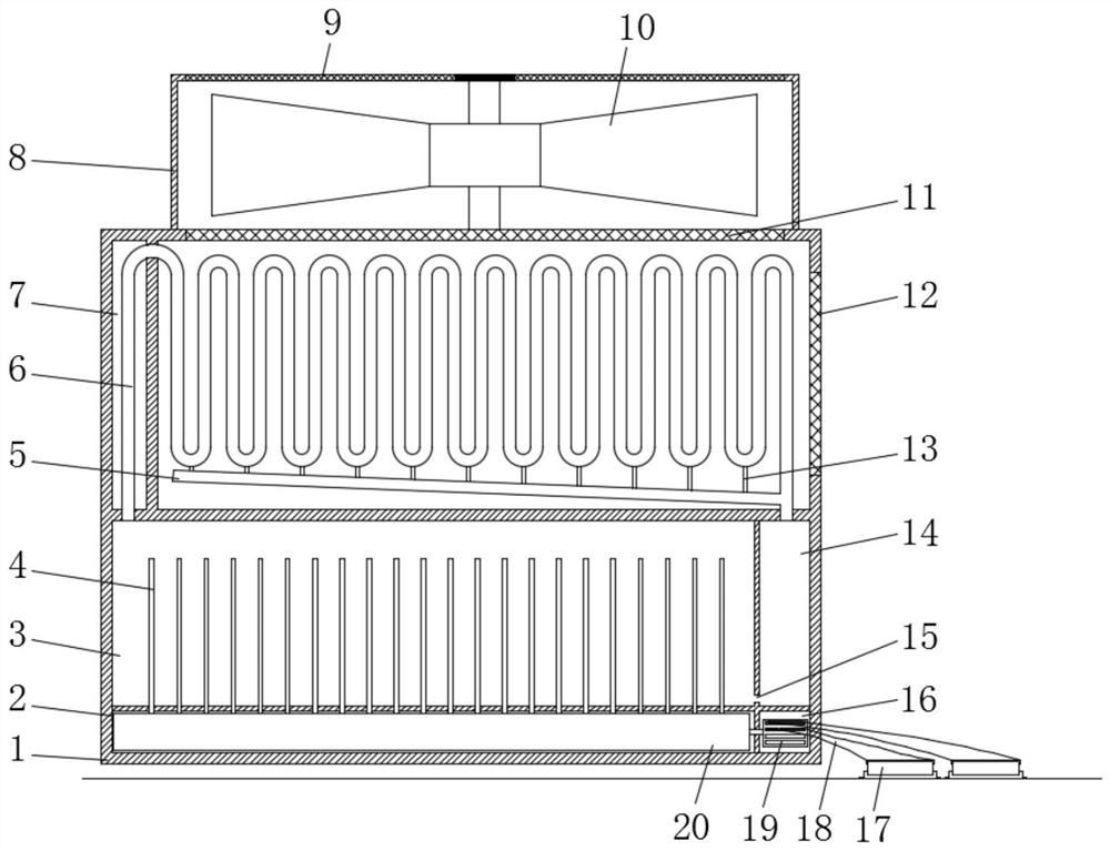
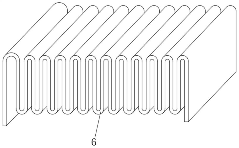
[0028] refer to Figure 1-4 , a high-efficiency heat dissipation device for electronic components, including a heat dissipation box 1 and an electronic component 17, a fan box 8 is installed on the upper end of the heat dissipation box 1, a fan 10 is installed in the fan box 8, and an upper top wall of the fan box 8 is embedded A third dust-proof net 9 is installed, and the heat dissipation box 1 is divided into a condensation chamber 7, a heat absorption chamber 3, a return chamber 14, a heating chamber 2, and a heat conduction module chamber 16, and a condensation heat dissipation mechanism is installed in the condensation chamber 7;
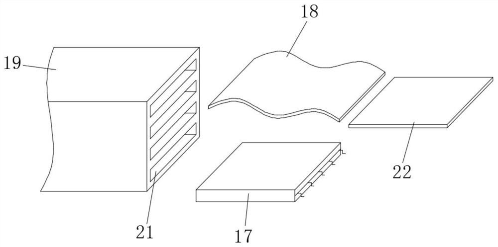
[0029] A heat conduction module block 19 is installed in the heat conduction module cavity 16, and a flexible graphite connecting sheet 18 is inserted on the heat conduction module block 19, and a plurality of slots 21 are symmetrically opened at both ends of the heat conduction module block 19, and the flexible graphite connection One end of ...
Embodiment 2
[0034] refer to Figure 5 , a high-efficiency heat dissipation device for electronic components provided in this embodiment is basically the same as Embodiment 1, the difference is that:
[0035] The upper bottom wall of the condensation chamber 7 is embedded with a first dust-proof net 11, and the side wall of the condensation chamber 7 is embedded with a second dust-proof net 12, and the first dust-proof net 11 communicates with the condensation chamber 7 and the outside air. , and the second dust-proof net 12 communicates with the fan box 8 and the condensation chamber 7, that is, the fan box 8 is installed on the outer wall of the condensation chamber 7, and the fan box 8 is installed on the side of the cooling box 1 to reduce the thickness of the cooling device and reduce the circuit. Board installation difficulty.
[0036] In this embodiment, according to the arrangement of the electronic components 17 that need to be dissipated on the circuit board, select a suitable f...
PUM
 Abstract
Description
Claims
Application Information
 - R&D
- Intellectual Property
- Life Sciences
- Materials
- Tech Scout
- Unparalleled Data Quality
- Higher Quality Content
- 60% Fewer Hallucinations
Browse by: Latest US Patents, China's latest patents, Technical Efficacy Thesaurus, Application Domain, Technology Topic, Popular Technical Reports.
© 2025 PatSnap. All rights reserved.Legal|Privacy policy|Modern Slavery Act Transparency Statement|Sitemap|About US| Contact US: help@patsnap.com


