Bearing arrangement for drive shaft of turbo-machine, and turbo-machine including such bearing arrangement

A technology of supporting structure and drive shaft, which is applied to components of pumping devices for elastic fluid, sliding contact bearings, machines/engines, etc., can solve problems such as increasing the manufacturing cost of turbo compressors

Active Publication Date: 2019-11-08
ROBERT BOSCH GMBH +1
View PDF15 Cites 5 Cited by
  • Summary
  • Abstract
  • Description
  • Claims
  • Application Information

AI Technical Summary

Problems solved by technology

[0013] Therefore, the setting of the gas bearing structure further increases the manufacturing cost of the turbo compressor

Method used


Image

  • Bearing arrangement for drive shaft of turbo-machine, and turbo-machine including such bearing arrangement
  • Bearing arrangement for drive shaft of turbo-machine, and turbo-machine including such bearing arrangement
  • Bearing arrangement for drive shaft of turbo-machine, and turbo-machine including such bearing arrangement

Examples


Embodiment Construction

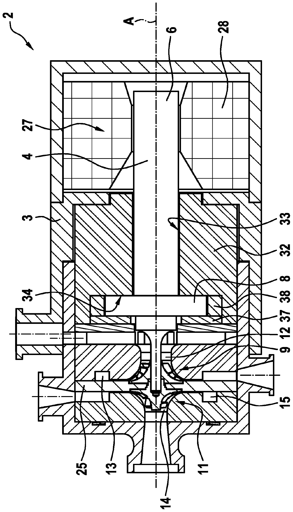
[0066] Figure 1 to Figure 3 A turbomachine 2 according to a first embodiment of the invention is represented, in particular a two-stage centrifugal turbocompressor.

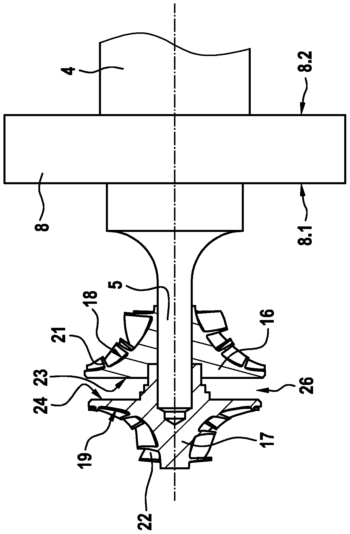
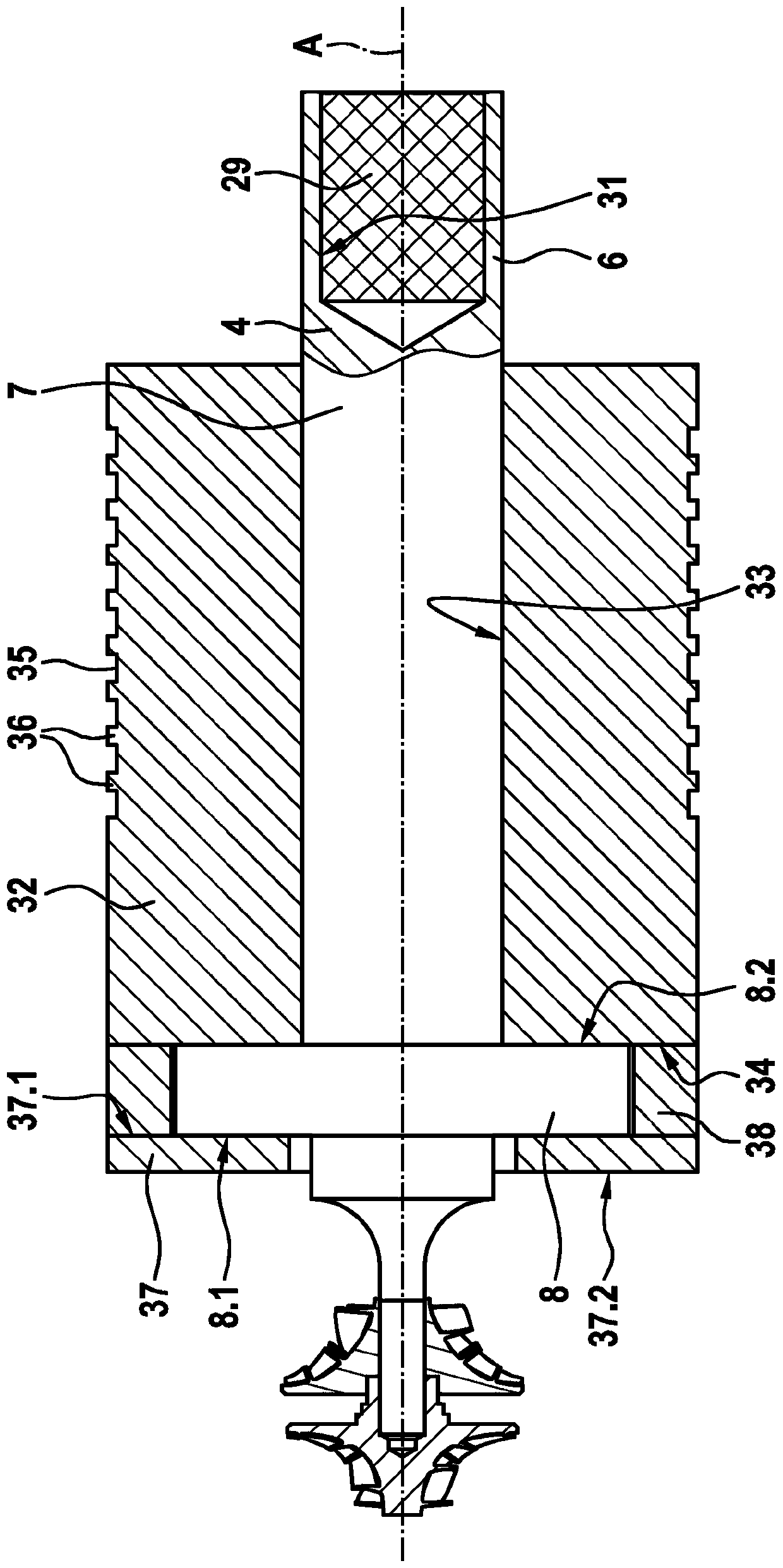
[0067] The turbine 2 comprises a housing 3 and a drive shaft 4 , which is rotatably arranged inside the housing 3 and extends along a longitudinal axis A. As shown in FIG. The drive shaft 4 includes an impeller portion 5 , a drive portion 6 opposite to the impeller portion 5 , and a bearing portion 7 arranged between the impeller portion 5 and the drive portion 6 .

[0068] The drive shaft 4 also comprises a radial thrust bearing member 8 , also referred to as a radial flange portion, which has the shape of a flat disc and extends radially outwards with respect to the bearing portion 7 . The radial thrust bearing member 8 has an outer diameter greater than that of the bearing portion 7 and comprises a first axial face 8.1 and a second axial face 8.2 opposite to the first axial face 8.1. The radial thrust suppo...


PUM

PropertyMeasurementUnit
Vickers hardnessaaaaaaaaaa

Abstract

The bearing arrangement includes a one-piece gas bearing sleeve (32) configured to rotatably support the drive shaft (4) and made in molybdenum or in a molybdenum alloy, the one-piece gas bearing sleeve (32) including a radial bearing surface (33) configured to Surround the drive shaft (4).

Description

technical field [0001] The present invention relates to a support structure for a drive shaft of a turbomachine, in particular to a centrifugal turbo compressor. Background technique [0002] Centrifugal turbo compressors are known to include: [0003] -shell, [0004] - a drive shaft rotatably arranged within the housing and extending along the longitudinal axis, the drive shaft comprising radial thrust bearing members, [0005] - a first compression stage and a second compression stage configured to compress a refrigerant, the first compression stage and the second compression stage respectively comprising a first impeller and a second impeller, the first impeller and the second impeller being connected to the drive shaft and arranged in a back-to-back configuration, [0006] - an axial bearing structure configured to limit the axial movement of the drive shaft during operation, the axial bearing structure comprising: [0007] - a first axial support plate and a second...

Claims


Application Information

Patent Timeline
Patent Type & Authority Applications(China)
IPC IPC(8): F04D17/12F04D29/02F04D29/051F04D29/057F16C33/12F01D25/16F01D25/22F16C17/02F16C17/04F16C33/10
CPCF16C2204/46F01D25/166F01D25/22F04D17/122F04D29/023F04D29/0513F04D29/057F16C17/02F16C17/04F16C33/1005F16C33/121F05D2300/131F01D25/125F04D29/056F16C3/02F16C2360/44
Inventor P·博纳富瓦C·马尔蒂尼亚戈Y·罗森S·范德斯蒂恩
Owner ROBERT BOSCH GMBH
Why Eureka
Try Eureka