
Multi-cutter mechanism and using method of high-efficiency precise cutting micro-structure and using method

A technology of precision cutting and fine structure, which is applied in the direction of metal processing machinery parts, large fixed members, metal processing equipment, etc. It can solve the problems of increasing the number of mold splicing, not being able to cut large molds, and affecting product quality, so as to reduce the number of splicing , avoiding the offset of the cutter head and improving the cutting efficiency

Pending Publication Date: 2019-11-12
YEAGOOD INC
View PDF9 Cites 2 Cited by
  • Summary
  • Abstract
  • Description
  • Claims
  • Application Information

AI Technical Summary

Problems solved by technology

[0005] However, the existing fly-cutting and planing methods all use a single tool, and the tool is easy to wear due to the microstructure size and cutting method, and the tool wear cannot be detected in time during the processing, which will cause waste products; Another problem caused by wear and tear is that it is impossible to cut large molds, while small molds will increase the splicing times of molds in subsequent work, which will greatly affect product quality; therefore, in order to reduce the scrap rate of mold processing and improve the final Product quality, the ability to cut large pieces of the original mold without changing the tool, is crucial for precision micro-cutting

Method used


Image

  • Multi-cutter mechanism and using method of high-efficiency precise cutting micro-structure and using method
  • Multi-cutter mechanism and using method of high-efficiency precise cutting micro-structure and using method
  • Multi-cutter mechanism and using method of high-efficiency precise cutting micro-structure and using method

Examples


Embodiment 1

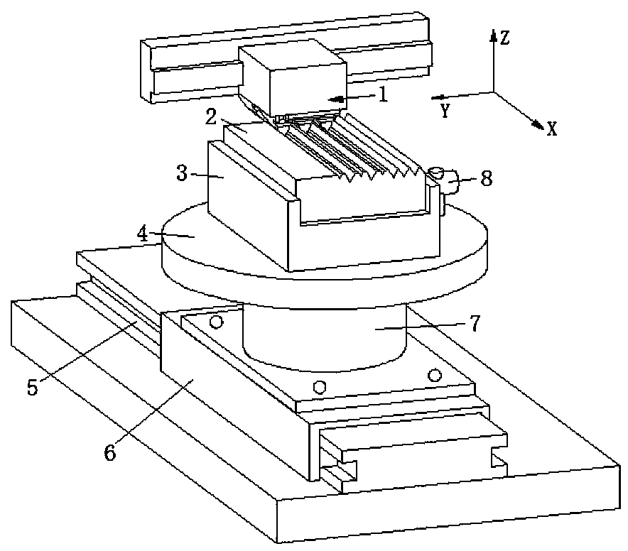
[0041] Such as Figure 4 As shown, the tool assembly 1 includes a first tool seat 11a, a tool mounting base 12, and a cutting head 13 fixed on the tool mounting base 12, the first tool seat 11a is fixed on the feed guide rail of the engraving machine tool, and the tool There are two installation bases 12, and the two tool installation bases 12 are fixed on the bottom of the first tool holder 11a;

Embodiment 2

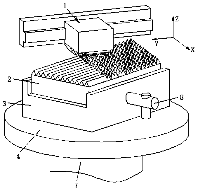
[0043] Such as Figure 5 As shown, the knife assembly 1 also includes a second knife seat 11b, the second knife seat 11b is welded to the front surface wall of the first knife seat 11a, and the structure of the second knife seat 11b is the same as that of the first knife seat 11a;

[0044] In summary, both the first tool seat 11a and the second tool seat 11b are hydraulic lifting devices, and the hydraulic drive can effectively realize the movement of the tool mounting base 12 and the cutting head 13, thereby facilitating the adjustment of the Z-axis feed amount; Among them, the cutter assembly 1 proposed in Embodiment 1 has a relatively small structure, and can be effectively applied to engraving machine tools with a small movable range.

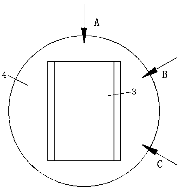
[0045] The workpiece assembly includes a workpiece driving device and a workpiece holder 3 installed on the workpiece driving device. The inside of the workpiece holder 3 is engaged with a workpiece 2. The top surface of the workpiece 2 is ...


PUM


Abstract

The invention belongs to the technical field of precision cutting processing, and discloses a multi-cutter mechanism and a using method of a high-efficiency precise cutting micro-structure. The multi-cutter mechanism comprises a cutter assembly and a workpiece assembly, wherein the cutter assembly comprises a first cutter holder, cutter mounting bases and cutting cutter heads fixed on the cutter mounting bases, the first cutter holder is fixed on a cutter feeding guide rail of an engraving machine tool, and two cutter mounting bases are arranged; the workpiece assembly comprises a workpiece driving device and a workpiece clamping seat arranged on the workpiece driving device; and the workpiece driving device comprises a linear driving device and a rotary driving device. According to the multi-cutter mechanism and the using method, the row-by-row multi-cutter structure is adopted, so that simultaneous cutting of a plurality of cutter heads is effectively realized, and therefore the purpose of improving the cutting efficiency is achieved; compared with a traditional single-head cutting, the mechanism can be suitable for larger workpieces or modules in the cutting process, so that theeffect of reducing the number of splicing times of workpieces or modules is achieved, and the quality of final finished products is effectively guaranteed.

Description

technical field [0001] The invention belongs to the technical field of precision cutting, and in particular relates to a multi-knife mechanism for high-efficiency and precise cutting of microstructures and a method of use thereof. Background technique [0002] The so-called precision machining refers to the processing technology with extremely high machining accuracy and surface quality. The most mature precision machining in the existing technology is lithography technology. However, the high price of lithography equipment leads to relatively high processing costs for corresponding workpieces. high. [0003] Taking the precision machining of microprism reflective arrays as an example, the existing processing methods mainly include pin clustering method, lamination method, and V-shaped groove cutting method; (1) pin clustering method: take a triangular prism whose two ends are equilateral triangles, Triangular pyramids are cut at the front end of the triangular prism, and t...

Claims


Application Information

Patent Timeline
IPC IPC(8): B23D79/00B23Q1/25
CPCB23D79/00B23Q1/25
Inventor 许明旗杨光皮钧黄志鹏黄志江
Owner YEAGOOD INC
Learn More