
Eureka
For R&D, Eureka makes reading and utilizing patents & technical documents easy.
Eureka AIR
Designed for self-driven R&D workflows. Generate viable solutions, solve complex R&D challenges, empower your innovation with AI.

Eureka Materials
Designed for material experts only. Revolutionize your material R&D, from search, analyze, to developing new materials.

TechResearch
Generate reliable direction feasibility study reports for your R&D in just a few steps.

TechSeek
Discover and master advanced knowledge NOW. Basics, ideas, possibilities, all at once.

TechMind
As an expert in R&D Theories, TechMind can generates customized viable solutions instantly.

TechRisk
Analyze your overall solution with one click, know your potential R&D risks in advance.

TechMonitor
Get weekly tech updates, stay abreast of the latest tech innovations and key insights.
Active carbon adsorption zone and water treatment pool
A technology of activated carbon adsorption and water treatment, which is applied in the fields of adsorption water/sewage treatment, water/sewage treatment, water/sewage multi-stage treatment, etc. Adsorption efficiency, avoiding clogging, and avoiding the effect of adsorption competition
- Summary
- Abstract
- Description
- Claims
- Application Information
AI Technical Summary
Problems solved by technology
Method used
Image


Examples
no. 1 example
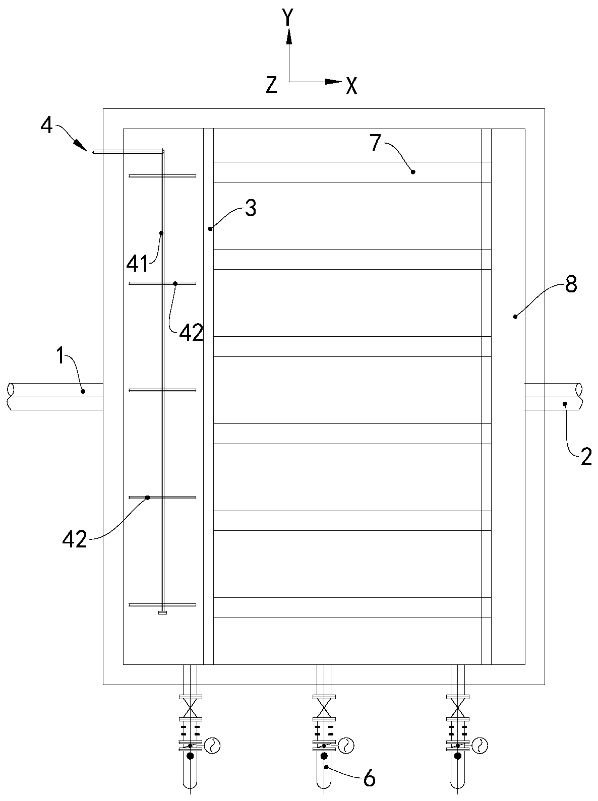
[0027] For the sake of clarity, the same spatial coordinate system is used in the following figures, so as to facilitate the understanding of the mutual positional relationship among the figures.
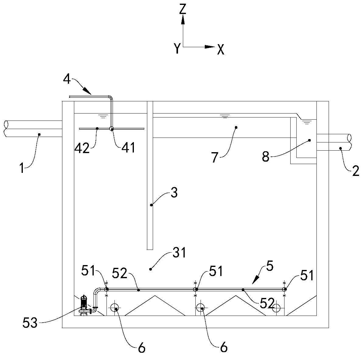
[0028] The area referred to in the present invention is essentially a pool capable of performing specific functions, and a plurality of areas with different functions constitute a complete water treatment pool. The activated carbon adsorption zone of this embodiment is referred to figure 1 , the activated carbon adsorption area is surrounded by the surrounding wall and the bottom of the area. The raw water from the upstream enters the rectification area on the left side of the suspension wall 3 from the water inlet pipe 1 as the water inlet. The powder feeding device 4 is arranged in the rectification area. A powder feeding pipe 41 and five powder feeding branch pipes 42 are formed. The center line of the powder feeding pipe 41 is in the Y axis. Seen from the XY plane, the water flo...
no. 2 example
[0032] The difference between this example and the previous example is that the anti-settling device 5 is composed of a tap water source with pressure and a plurality of showers evenly distributed at the bottom of the activated carbon adsorption area. Each shower is connected with the tap water source through a pipeline, and each The showers all spray towards the negative direction of the Z axis.
no. 3 example
[0034] The difference between this example and the first example is that the volume of the activated carbon adsorption area is relatively small, and the size of the rectification area in the X-axis direction is relatively small, so only the powder feeding pipe 41 is provided and the powder feeding branch pipe 42 is cancelled.
PUM
 Abstract
Description
Claims
Application Information
 - R&D Engineer
- R&D Manager
- IP Professional
- Industry Leading Data Capabilities
- Powerful AI technology
- Patent DNA Extraction
Browse by: Latest US Patents, China's latest patents, Technical Efficacy Thesaurus, Application Domain, Technology Topic, Popular Technical Reports.
© 2024 PatSnap. All rights reserved.Legal|Privacy policy|Modern Slavery Act Transparency Statement|Sitemap|About US| Contact US: help@patsnap.com