Supercharge Your Innovation With Domain-Expert AI Agents!

Fusion method and device for yaw angle and aerial vehicle

A technology of yaw angle and aircraft, applied in the field of aircraft, can solve the problem of large error in primary complementary filtering

Active Publication Date: 2019-11-12
SHENZHEN AUTEL INTELLIGENT AVIATION TECH CO LTD
View PDF6 Cites 9 Cited by
  • Summary
  • Abstract
  • Description
  • Claims
  • Application Information

AI Technical Summary

Problems solved by technology

[0004] Embodiments of the present invention provide a yaw angle fusion method, device, and aircraft, which solve the technical problem of large complementary filtering errors and improve the fusion accuracy and stability of yaw angles

Method used


Image

  • Fusion method and device for yaw angle and aerial vehicle
  • Fusion method and device for yaw angle and aerial vehicle
  • Fusion method and device for yaw angle and aerial vehicle

Examples


Embodiment 1

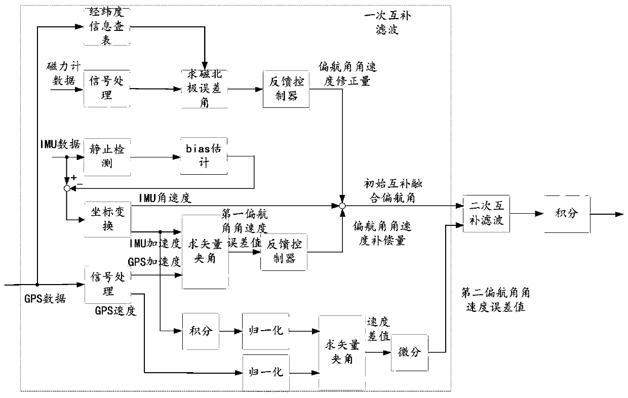
[0141] see figure 2 , figure 2 It is a functional block diagram of a yaw angle fusion method provided by an embodiment of the present invention;

[0142] Such as figure 2 As shown, by obtaining GPS data, magnetometer data and IMU data, and according to the GPS data, the longitude and latitude information look-up table is performed, and the magnetometer data is signal-processed to obtain the magnetic north pole error angle, and the magnetic north pole The error angle generates the yaw angular velocity correction amount through the feedback of the feedback controller, and obtains the IMU angular velocity through the IMU data, obtains the yaw angular velocity compensation amount through the GPS data and the IMU data, and corrects the yaw angular velocity Quantity, IMU angular velocity, and yaw angular velocity compensation are fused to generate an initial complementary fusion yaw angle, and by integrating the IMU acceleration and normalizing the integrated velocity, the GPS ...

Embodiment 2

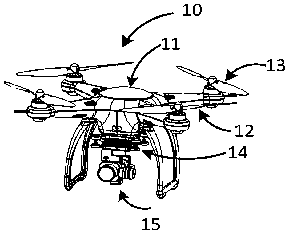
[0233] see Figure 11 , Figure 11 It is a schematic diagram of a yaw angle fusion device provided by an embodiment of the present invention;

[0234] Such as Figure 11 As shown, the fusion device 110 of the yaw angle is applied to an aircraft, specifically, the fusion device 110 of the yaw angle may be a flight controller of the aircraft, and the device includes:

[0235] Obtaining module 111, for obtaining magnetometer data, IMU data, GPS data, described IMU data comprises IMU acceleration information and IMU angular velocity information, and described GPS data comprises GPS velocity information and GPS acceleration information;

[0236] A yaw angular velocity correction amount module 112, configured to determine a yaw angular velocity correction amount according to the GPS data and the magnetometer data;

[0237] The first yaw rate error value module 113 is used to determine the first yaw rate error value according to the IMU acceleration information and the GPS acceler...


PUM


Abstract

The invention relates to the technical field of an aerial vehicle and discloses a fusion method and device for a yaw angle and the aerial vehicle. The method comprises the steps of obtaining magnetometer data, IMU (Inertial Measurement Unit) data and GPS data; determining a yaw angle velocity correction quantity according to the GPS data and the magnetometer data; determining a first yaw angle velocity error value according to IMU acceleration information and GPS acceleration information; determining an initial complementary fused yaw angle velocity according to IMU angle velocity information,the yaw angle velocity correction quantity and the first yaw angle velocity error value; and determining a second yaw angle velocity error value according to the IMU acceleration information and GPSspeed information; and determining a final complementary fused yaw angle according to the initially complementary fused yaw angle velocity and the second yaw angle velocity error value. In the mode, according to the method and the device, the technical problem that single-time complementary filtering error is relatively great is solved, and fusion precision and stability of the yaw angle are improved.

Description

technical field [0001] The invention relates to the technical field of aircraft, in particular to a yaw angle fusion method, device and aircraft. Background technique [0002] Aircraft, such as unmanned aerial vehicles (Unmanned Aerial Vehicle, UAV), also known as unmanned aerial vehicles (UAVs), have gained more and more attention due to their advantages such as small size, light weight, flexible maneuverability, quick response, unmanned driving, and low operating requirements. Wide range of applications. Each action (or attitude) of the unmanned aerial vehicle is usually realized by controlling the different rotational speeds of a plurality of drive motors in the power plant of the unmanned aerial vehicle. Among them, the yaw angle is an important parameter in controlling the flight attitude of the UAV, that is, the yaw angle fusion of the UAV is especially important for the attitude control of the UAV. If the yaw angle fusion error of the UAV If the fusion accuracy is t...

Claims


Application Information

Patent Timeline
Patent Type & Authority Applications(China)
IPC IPC(8): G01C21/20G01C21/16G05D1/08
CPCG05D1/0816G01C21/20G01C21/165B64U10/14B64U30/20B64U50/19G01C21/1654B64D27/02B64U2201/10B64U2101/30
Inventor 张添保李颖杰
Owner SHENZHEN AUTEL INTELLIGENT AVIATION TECH CO LTD
Features
  • R&D
  • Intellectual Property
  • Life Sciences
  • Materials
  • Tech Scout
  • Unparalleled Data Quality
  • Higher Quality Content
  • 60% Fewer Hallucinations
Learn More