
Guided wave radar level meter

A technology of guided wave radar and level meter, which is applied in the direction of liquid/fluid solid measurement, engine lubrication, instruments, etc. It can solve the problems of inconvenient installation of wave radar meter, achieve improved stability, simple device structure, and easy installation Effect

Inactive Publication Date: 2019-11-12
陕西诺盈自动化仪表有限公司
View PDF0 Cites 4 Cited by
  • Summary
  • Abstract
  • Description
  • Claims
  • Application Information

AI Technical Summary

Problems solved by technology

[0003]It is generally installed at the mouth of the tank, but due to the different sizes of the tank mouth to be installed, it is inconvenient to install the guided wave radar meter

Method used


Image

  • Guided wave radar level meter
  • Guided wave radar level meter

Examples


Embodiment 1

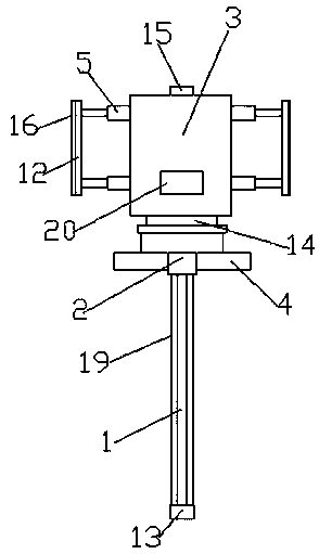
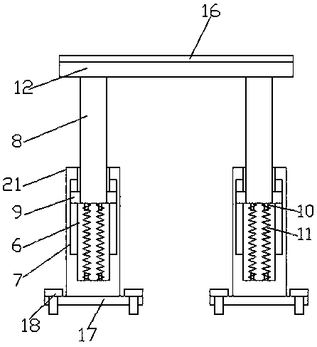
[0028] see Figure 1-2 , a guided wave radar level gauge according to an embodiment of the present invention includes a probe 1, a probe 13 is connected to the bottom end of the probe 1, and a connecting block 2 is provided at the top of the probe 1, and the The connection block 2 is provided with a meter head 3, and a signal processing chamber 14 is arranged below the meter head 3, and the signal processing chamber 14 is connected to the probe 1 through the connection block 2, and the outside of the connection block 2 A fixed plate 4 is provided, and installation devices 5 are provided on both sides of the meter head 3, and the installation device 5 includes two first installation rods 21 in number, and cavities are provided in the first installation rods 21 6. Both sides of the inner wall of the cavity 6 are provided with chute 7, the cavity 6 is provided with a second installation rod 8, and the second installation rod 8 is located on both sides of one end of the cavity 6 ...

Embodiment 2

[0031] Such as Figure 1-2 As shown, the meter head 3 is provided with a cable installation port 15, which is convenient for cable installation; the installation plate 12 is provided with an elastic gasket 16, which can improve the stability of the installation; There is a fixed plate 17, and the fixed plate 17 is symmetrically provided with threaded nails 18, and the fixed plate 17 is detachably connected with the meter head 3 through the threaded nails 18, so as to facilitate the installation and disassembly of the first installation rod 21; A protective case 19 is provided outside the probe 1, and the protective case 19 is fixedly installed on the connection block 2, which can protect the probe 1; a data transmitter 20 is provided on the meter head 3, The data transmitter 20 is electrically connected with an external data receiver, so as to transmit the detected data.

[0032] In order to facilitate the understanding of the above-mentioned technical solution of the present...


PUM


Abstract

The invention discloses a guided wave radar level meter. The guided wave radar level meter comprises a guided wave rod, mounting devices are arranged at two sides of a gauge outfit, each mounting device comprises two first mounting rods, cavities are arranged in the first mounting rods; sliding chutes are arranged at two sides of each cavity, a second mounting rod is arranged in each cavity; sliding blocks are arranged at two sides of one end, in the cavity, of each second mounting rod, limiting posts are arranged on the bottom end of each second mounting rod and the bottom of the inner wall of each cavity; pressure springs are connected between the limiting posts; a mounting plate is connected between top ends of the second mounting rods; in the mounting, the second mounting rods are inward compressed by utilizing the elasticity of the pressure springs and the cooperation of the sliding blocks and the sliding chutes, thereby obtaining the length matched with a tank opening; and the effect of fixing the guided wave radar level meter can be achieved by utilizing the elasticity of the pressure springs; and the device has the advantages of being simple in structure and convenient to mount and can be adapted to different tank opening sizes.

Description

technical field [0001] The invention relates to the technical field of radar liquid level gauges, in particular to a guided wave radar level gauge. Background technique [0002] Guided wave radar level gauge is a liquid level measuring instrument commonly used in the chemical industry. Guided wave radar level gauge is a radar level gauge based on the principle of time domain reflection. Guided wave radar is a measuring instrument based on the principle of time travel. Radar waves run at the speed of light, and the running time can be replaced by electronic components. The high-frequency pulse is transmitted along the cable or rod probe. When the pulse meets the surface of the material, it is reflected back and received by the receiver in the instrument, and the distance signal is changed into a level signal. The electromagnetic pulse of the guided wave radar level gauge propagates along the guide rod or waveguide cable at the speed of light. When encountering the surface of...

Claims


Application Information

Patent Timeline
Patent Type & Authority Applications(China)
IPC IPC(8): G01F23/284
CPCG01F23/284
Inventor 李军荣
Owner 陕西诺盈自动化仪表有限公司
Learn More