Eureka AIR delivers breakthrough ideas for toughest innovation challenges, trusted by R&D personnel around the world.

Paddle pressure monitoring system based on optical fiber sensor and paddle

An optical fiber sensor and pressure monitoring technology, which is applied in the application of optical methods for fluid pressure measurement, fluid pressure measurement, and force measurement by measuring the change of optical properties of materials when they are stressed. The problem of large error and high price can achieve the effect of reducing cost, improving practicability and easy reuse

Pending Publication Date: 2019-11-12
SHENZHEN TECH UNIV
View PDF0 Cites 1 Cited by
  • Summary
  • Abstract
  • Description
  • Claims
  • Application Information

AI Technical Summary

Problems solved by technology

[0003] At present, there are mainly two methods for detecting and measuring the force on the blade: the first method is to measure the acceleration of the ship to draw a graph of the change of thrust. Although this method is useful, it is affected by the weather conditions The influence of the measurement results is large and the error of the measurement result cannot fully reflect the change of the thrust; the second method is to measure the thrust through the stress gauge or accelerometer installed on the blade or embedded in the blade. Although this method can detect the blade However, due to the high price and the limited length of the blade, it cannot be used in a wide range

Method used


Image

  • Paddle pressure monitoring system based on optical fiber sensor and paddle
  • Paddle pressure monitoring system based on optical fiber sensor and paddle
  • Paddle pressure monitoring system based on optical fiber sensor and paddle

Examples


Embodiment Construction

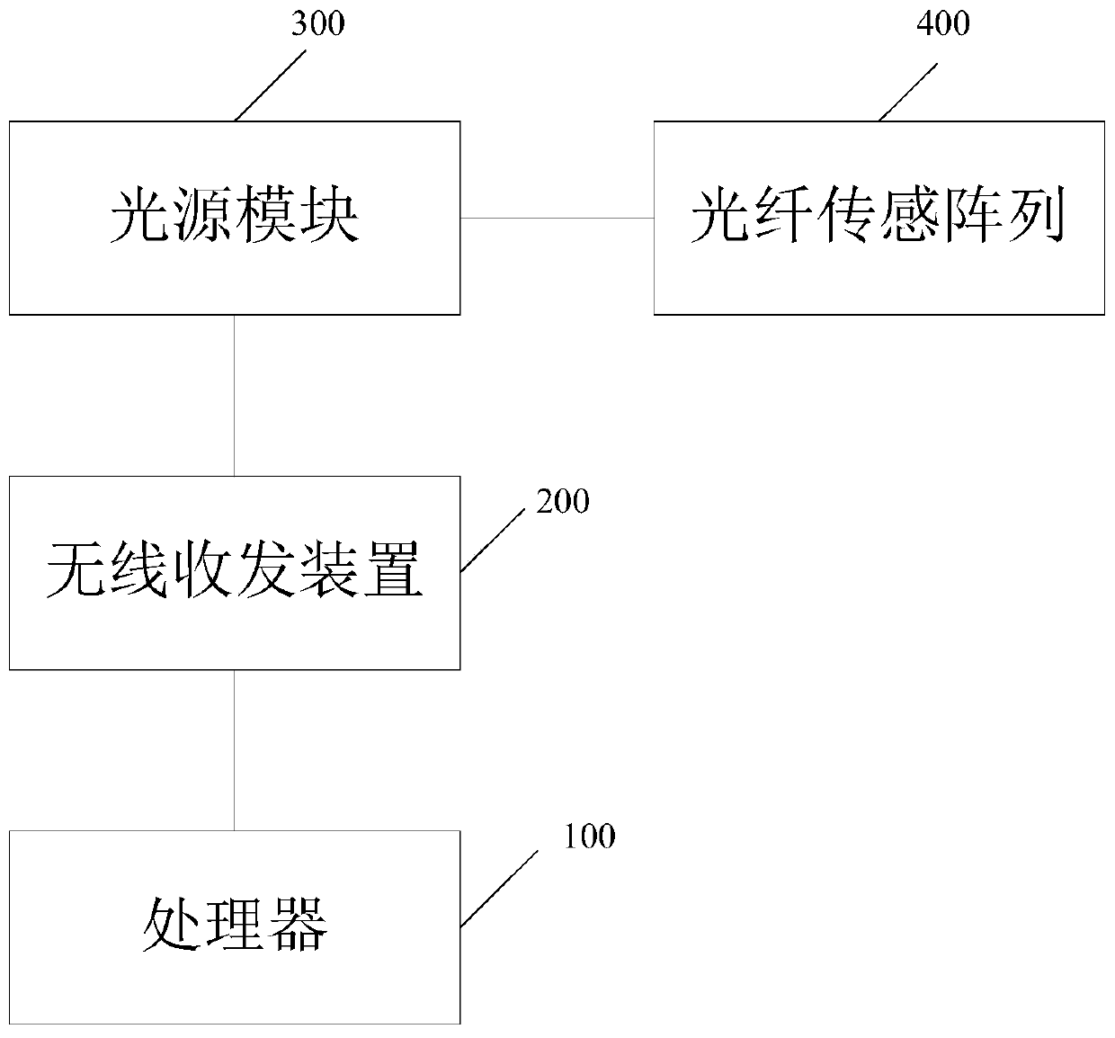
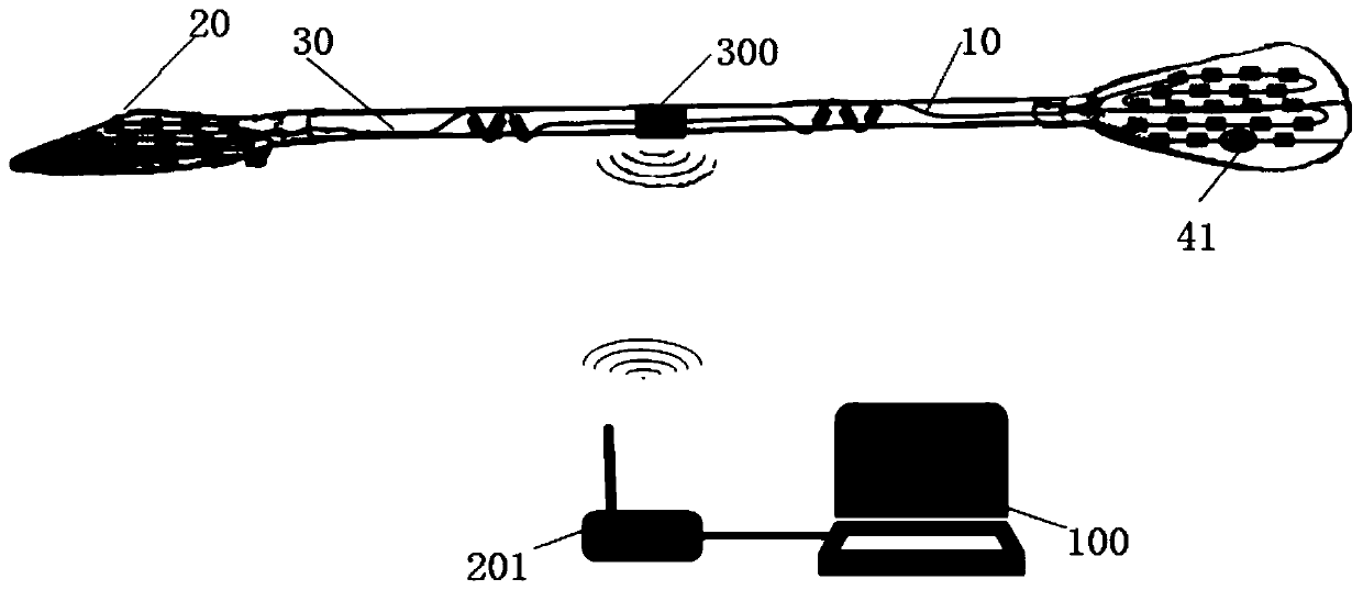
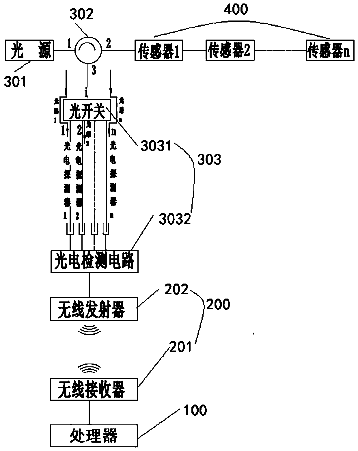
[0022] The present invention provides a blade pressure monitoring system based on an optical fiber sensor and blades. In order to make the purpose, technical solution and effect of the present invention clearer and clearer, the present invention will be further described in detail below with reference to the accompanying drawings and examples. It should be understood that the specific embodiments described here are only used to explain the present invention, not to limit the present invention.

[0023] It should be noted that when a component is referred to as being “fixed on” or “disposed on” another component, it may be directly on the other component or indirectly on the other component. When an element is referred to as being "connected to" another element, it can be directly connected to the other element or indirectly connected to the other element.

[0024] It should also be noted that the same or similar symbols in the drawings of the embodiments of the present inventi...


PUM

PropertyMeasurementUnit
wavelengthaaaaaaaaaa

Abstract

The invention discloses a paddle pressure monitoring system based on an optical fiber sensor. The paddle pressure monitoring system based on the optical fiber sensor includes a processor, a wireless transceiver, and an optical fiber sensing array and a light source module which are arranged on a paddle; the light source module is connected to the optical fiber sensing array through an optical fiber, the light source module transmits the light to the optical fiber sensing array through the optical fiber, and sends an electrical signal formed according to the reflected light of the optical fibersensing array to the processor through the wireless transceiver; and the processor determines the paddle pressure according to the electrical signal. The paddle pressure monitoring system based on the optical fiber sensor adopts the optical fiber sensing array and monitors the paddle pressure distribution information in real time by detecting the wavelength displacement of the optical fiber sensing array; on the one hand, the problem that the traditional measurement method cannot solve and an additional underwater camera is required is solved, which reduces the cost of the monitoring system;on the other hand, the monitoring accuracy of the monitoring system is not affected by the intensity of the light source, and the reuse is easier, which improves the practicality of the monitoring system.

Description

technical field [0001] The invention relates to the technical field of optical fiber sensing, in particular to a blade pressure monitoring system and blade based on an optical fiber sensor. Background technique [0002] Kayaking, rowing, dragon boat, etc. are all popular water sports. Both professional athletes and amateurs hope to row faster and get better results. In the above-mentioned water sports, the thrust and resistance of the blade are the most important factors, so in order to improve the effectiveness of paddling, it is very important to detect and measure the force of the blade in real time. [0003] At present, there are mainly two methods for detecting and measuring the force on the blade: the first method is to measure the acceleration of the ship to draw a graph of the change of thrust. Although this method is useful, it is affected by the weather conditions The influence of the measurement results is large and the error of the measurement result cannot full...

Claims


Application Information

Patent Timeline
Patent Type & Authority Applications(China)
IPC IPC(8): G01L11/02G01L1/24
CPCG01L11/025G01L1/246
Inventor 陈志超何铁锋万刘伟马正宜向子瑒周祝鑫
Owner SHENZHEN TECH UNIV
Why Eureka
Eureka Blog
Learn More