Battery thermal management system for vehicle

A battery thermal management and vehicle technology, applied in the field of vehicle battery thermal management system, can solve the problems of poor cooling effect, high cost, high energy consumption, etc., and achieve the effect of prolonging service life, good cooling effect and high heat exchange efficiency

Active Publication Date: 2019-11-12
ZHEJIANG GEELY HLDG GRP CO LTD +1
View PDF8 Cites 1 Cited by
  • Summary
  • Abstract
  • Description
  • Claims
  • Application Information

AI Technical Summary

Problems solved by technology

The air-cooled power battery cooling system uses the cooling fan to suck the air from the inside of the car into the power battery pack to cool the battery. When using this cooling system to adjust the temperature of the battery, it largely depends on the air temperature in the car. , the cooling effect is not good, and an additional heating device is required to heat the battery at low temperature, the heating efficiency is not high, resulting in unstable performance of the power battery
Liquid cooling and direct cooling have better cooling effects, but additional heating devices are required at low temperatures, and the entire system is complex, costly, and energy-consuming
[0004] Therefore, the existing battery thermal management system has the problems of poor cooling effect, complex system and high cost

Method used


Image

  • Battery thermal management system for vehicle
  • Battery thermal management system for vehicle
  • Battery thermal management system for vehicle

Examples


Embodiment Construction

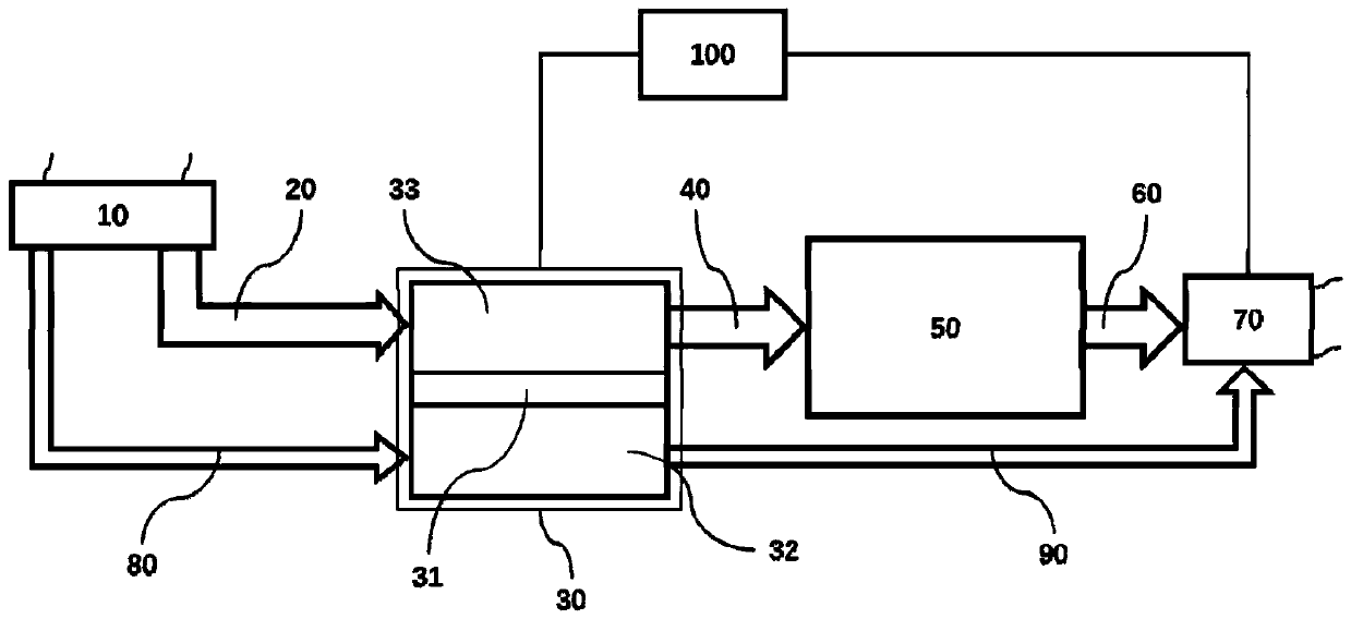
[0039] figure 1 is a schematic structural diagram of a battery thermal management system according to an embodiment of the present invention. Such as figure 1 As shown, the present invention provides a vehicle battery thermal management system, which may generally include a thermoelectric semiconductor heat exchange unit 30 , a battery pack 50 , a fan unit 70 and a control unit 100 . The thermoelectric semiconductor heat exchange unit 30 includes a thermoelectric semiconductor 31 , a first air heat exchanger 33 and a second air heat exchanger 32 respectively disposed on opposite first and second ends of the thermoelectric semiconductor 31 . Here, the first end and the second end refer to the heat exchange ends of the thermoelectric semiconductor 31, for example, when a preset voltage is applied to the thermoelectric semiconductor 31, the first end starts to cool while the second end starts to heat; When the preset voltage is applied to the thermoelectric semiconductor 31, th...


PUM


Abstract

The invention provides a battery thermal management system for a vehicle and belongs to the field of batteries. The system comprises: a thermoelectric semiconductor heat exchange unit including a thermoelectric semiconductor, a first air heat exchanger and a second air heat exchanger, wherein the first air heat exchanger has one end connected to a first air inlet pipeline and the other end connected to a first air outlet pipeline, the second air heat exchanger has one end connected to a second air inlet pipeline and the other end connected to a second air outlet pipeline; a battery pack havingone end connected to the first air outlet pipeline and the other end connected to a third air outlet pipeline; a fan unit disposed downstream of the third air outlet pipeline and the second air outlet pipeline and configured to discharge the airflow of the third air outlet pipeline and the second air outlet pipeline out of the vehicle; and a control unit connected to the thermoelectric semiconductor heat exchange unit and the fan unit and configured to control the voltage applied to the thermoelectric semiconductor and the power of the fan unit according to the temperature of the battery pack. The battery thermal management system of the invention has a good cooling effect, a simple system and low cost.

Description

technical field [0001] The invention relates to the field of batteries, in particular to a battery heat management system for vehicles. Background technique [0002] At present, the commercially available power batteries for electric vehicles are mainly lithium-ion batteries. Since the performance of lithium-ion batteries is highly sensitive to temperature, if the temperature is lower or higher than the operating temperature range of the battery pack, the performance of the battery pack will decrease. A more pronounced decline occurred. Therefore, it is very important to cool or heat the battery pack so as to maintain it within the normal operating range. [0003] Currently, the commonly used cooling methods for on-board batteries mainly include: air-cooled, liquid-cooled, and direct-cooled. The air-cooled power battery cooling system uses the cooling fan to suck the air from the interior of the compartment into the power battery pack to cool the battery. When using this c...

Claims


Application Information

Patent Timeline
Patent Type & Authority Applications(China)
IPC IPC(8): H01M10/613H01M10/615H01M10/625H01M10/635H01M10/6556H01M10/6563H01M10/6572B60L58/26B60L58/27
CPCB60L58/26B60L58/27H01M10/613H01M10/615H01M10/625H01M10/635H01M10/6556H01M10/6563H01M10/6572Y02E60/10Y02T10/70
Inventor 郭灵聪杨林陈渊博
Owner ZHEJIANG GEELY HLDG GRP CO LTD
Why Eureka
Try Eureka