
Switch system fault protection method and device

A system failure and switch technology, applied in transmission systems, data exchange networks, digital transmission systems, etc., can solve problems such as inability to prompt error messages, analysis of unfavorable failures, etc., to prevent device burnout, avoid irreversible damage, increase The effect of hardware resource usage

Active Publication Date: 2019-11-12
INSPUR SUZHOU INTELLIGENT TECH CO LTD
View PDF6 Cites 7 Cited by
  • Summary
  • Abstract
  • Description
  • Claims
  • Application Information

AI Technical Summary

Problems solved by technology

At the same time, since CPLD / FPGA does not record error information, BMC cannot prompt error information, which is also not conducive to fault analysis

Method used


Image

  • Switch system fault protection method and device
  • Switch system fault protection method and device
  • Switch system fault protection method and device

Examples


Embodiment Construction

[0034] While the invention may be embodied in various forms, some exemplary and non-limiting embodiments are shown in the drawings and will be described below, it should be understood that the disclosure is to be considered as exemplary and not It is intended that the invention be limited to the specific embodiments described.

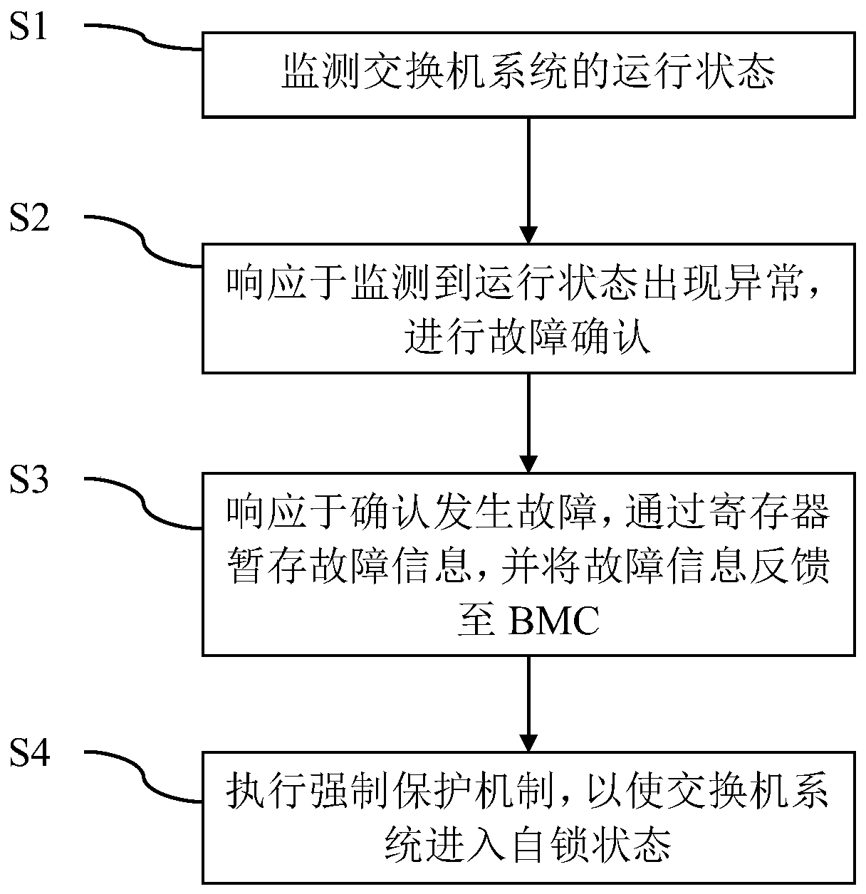
[0035] figure 1 A schematic block diagram of an embodiment of a method for protecting a switch system from failure according to the present invention is shown. As shown in the figure, an embodiment of the method at least includes performing the following steps based on a programmable device:

[0036] S1: Monitor the running status of the switch system;

[0037] S2: Carrying out fault confirmation in response to abnormalities detected in the operating state;

[0038] S3: In response to confirming that a fault occurs, temporarily store the fault information through the register, and feed back the fault information to the BMC;

[0039] S4: Execute the...


PUM


Abstract

The invention relates to a switch system fault protection method. The fault protection method for a switch system. The fault protection method comprises the following steps executed based on a programmable device: monitoring the running state of the switch system; in response to monitoring that the operation state is abnormal, carrying out fault confirmation; in response to confirmation of a fault, temporarily storing fault information through a register, and feeding back the fault information to the BMC; and executing a forced protection mechanism to enable the switch system to enter a self-locking state. Through the method provided by the invention, when a fault occurs, a certain measure is taken before VR response to protect the switch system and record fault information for subsequentprocessing.

Description

technical field [0001] The invention relates to the technical field of switch monitoring. The present invention further relates to a fault protection method and device for a switch system based on a programmable device and a BMC. Background technique [0002] In the switch system, the power-on and power-off sequence control, communication control, button detection, fan speed control, SFP lighting control and serial port switching of the entire switch are controlled through the CPLD / FPGA chip, and the switch status, firmware upgrade, and remote control are indicated through the BMC. and log collection. Realize signal monitoring based on CPLD / FPGA chip, control the power status of the whole switch at the same time, cooperate with BMC to realize signal display, in order to realize fault diagnosis and remind customers of the fault location, the above is of great significance for realizing the operation safety and troubleshooting of the whole switch system. [0003] CPLD / FPGA (...

Claims


Application Information

Patent Timeline
Patent Type & Authority Applications(China)
IPC IPC(8): H04L12/24H04L12/931G06F15/78
CPCH04L41/0681H04L49/10G06F15/7867
Inventor 薛广营季冬冬张广乐
Owner INSPUR SUZHOU INTELLIGENT TECH CO LTD
Learn More