
Instant use side plate connecting hole structure of storage cabinet

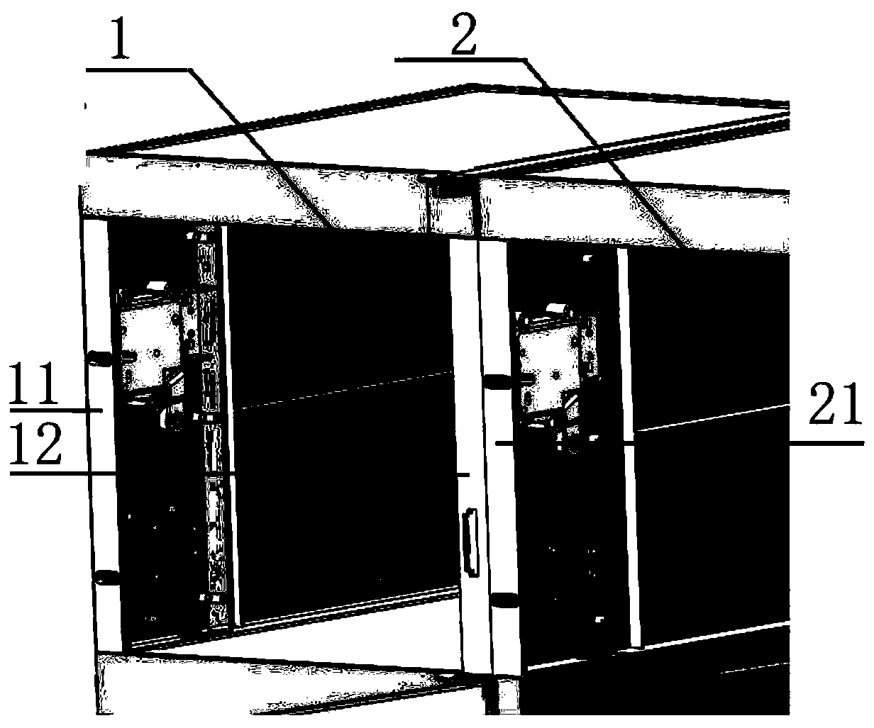
A locker and connecting hole technology, which is applied in the field of side plate connecting hole structure, can solve problems such as tilting or even falling of the cabinet row, time-consuming and laborious assembly, and inconvenient transportation, so as to improve safety, secure connection, and improve visual experience effect of effect

Pending Publication Date: 2019-11-15
德红柜智能科技(厦门)有限公司
View PDF0 Cites 0 Cited by
  • Summary
  • Abstract
  • Description
  • Claims
  • Application Information

AI Technical Summary

Problems solved by technology

[0003] However, for traditional lockers, the panels are fixed by screws or other methods, and are generally transported as a whole during transportation, but due to the large size, transportation is extremely inconvenient. It is time-consuming and labor-intensive to disassemble and transport, and then reassemble, which adds a lot of unnecessary costs, so it needs to be improved
[0004] At present, most of the lockers in the market are independent cabinets. According to the needs of movement and placement, manufacturers produce small and single lockers. There are often deviations, irregularities, or even slipping when they are combined together. There is a safety hazard between the combined cabinet rows, and there may be a danger of a certain cabinet row tilting or even falling down between the locker rows.

Method used


Image

  • Instant use side plate connecting hole structure of storage cabinet
  • Instant use side plate connecting hole structure of storage cabinet
  • Instant use side plate connecting hole structure of storage cabinet

Examples


specific Embodiment approach

[0051] Firstly, each annular rib 403 is concentric with the corresponding circular sheet, and the ratio of its inner diameter to the diameter of the circular sheet is 1.2-3.5.

[0052] Its two, the difference between the inner radius and the outer radius of the annular reinforcing rib 403 is 1-7mm, preferably 2-4mm, and the height is 0.5-5mm, preferably 1.5-3mm, and its inner diameter is the same as the diameter of the circular sheet The ratio is 2.0-2.8, preferably 2.3-2.5.

[0053] Third, the ratio of the thickness of each circular sheet (ie the preformed part) to the thickness of the side plate is 0.2-0.8, preferably 0.3-0.5.

[0054] Fourth, each annular reinforcing rib 403 is an arc-shaped surface, which has a better effect of preventing warped skin from cracking.

[0055] The present invention obtains the connecting hole 400 through the following implementation manners, specifically as follows:

[0056] During implementation, according to the requirements of the combin...


PUM


Abstract

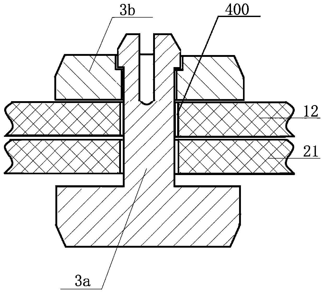
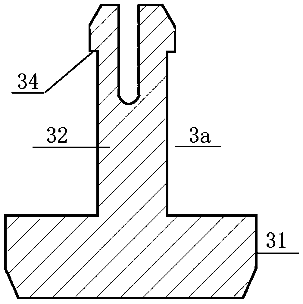
The invention discloses an instant use side plate connecting hole structure of a storage cabinet. The instant use side plate connecting hole structure of the storage cabinet comprises a side plate ofthe storage cabinet and a thin flaky pre-forming part, wherein the thin flaky pre-forming part is connected with the peripheral direction of the side plate and is integrally formed with the side plate, so that the pre-forming part receives the external force effect in the thickness direction, and the outer edge of the pre-forming part and the side plate are mutually separated. The pre-shaping partis a round thin flake; a projected cylindrical stress post extending in the axial direction of the round thin flake is arranged in the circle center position of the round thin flake; an annular stress concentration groove is formed between the cylindrical stress post and the outer edge of the round thin flake; the end part of the cylindrical stress post is provided with a positioning groove inwards recessed in the direction along the annular stress concentration groove; the positioning groove is a reverse conical groove; and annular reinforcing bars which surround the round thin flake in theperipherical direction and are projected towards the inner side surface of the round thin flake in the thickness direction of the round thin flake are arranged around the round thin flake.

Description

technical field [0001] The invention belongs to the field of door cabinets, and in particular relates to a ready-to-use side plate connecting hole structure of a locker. Background technique [0002] At present, with the development and progress of science and technology, lockers can be seen everywhere, in shopping malls, supermarkets, residential areas, bathrooms and even office halls. The lockers are arranged vertically by the roof and divided into several door cabinets. The box body is used for temporarily storing objects. It can be seen that the locker greatly facilitates people's storage and use. [0003] However, for traditional lockers, the panels are fixed by screws or other methods, and are generally transported as a whole during transportation, but due to the large size, transportation is extremely inconvenient. It is time-consuming and laborious to disassemble and transport, and then reassemble, which adds a lot of unnecessary costs, so it needs to be improved. ...

Claims


Application Information

Patent Timeline
Patent Type & Authority Applications(China)
IPC IPC(8): A47B96/04F16B5/06
CPCA47B96/04F16B5/0642
Inventor 杨华锋
Owner 德红柜智能科技(厦门)有限公司
Learn More