Fixing device for machining automobile beam middle plate

A technology of automobile girders and fixing devices, which is applied to workbenches, manufacturing tools, coil springs, etc., can solve problems such as inconvenient operation and impact on production efficiency, and achieve the effects of convenient operation, high practicability, and good lighting effects

Inactive Publication Date: 2019-11-15
十堰市乾德工贸有限公司
View PDF0 Cites 3 Cited by
  • Summary
  • Abstract
  • Description
  • Claims
  • Application Information

AI Technical Summary

Problems solved by technology

[0003] With the increasing demand for cars in the market, more and more automobile manufacturers have appeared. In the automobile production process, the processing of the middle plate of the automobile frame is often involved. In the process of processing the middle plate of the automobile frame, often It needs to be fixed with a fixing device. The existing fixing device needs to be manually turned over when it is fixed, which is inconvenient to operate and affects production efficiency

Method used


Image

  • Fixing device for machining automobile beam middle plate
  • Fixing device for machining automobile beam middle plate
  • Fixing device for machining automobile beam middle plate

Examples


Embodiment 1

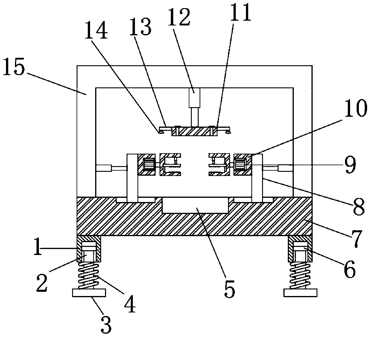
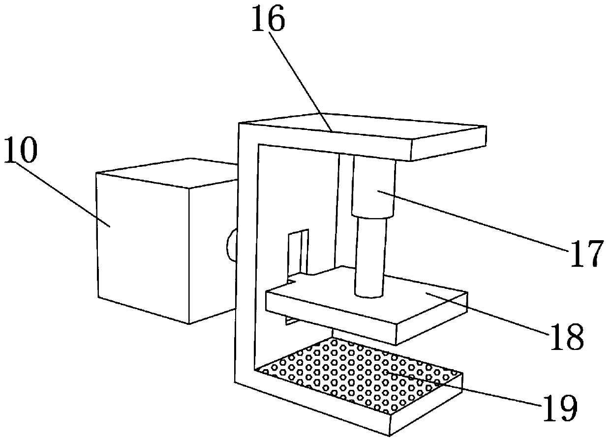
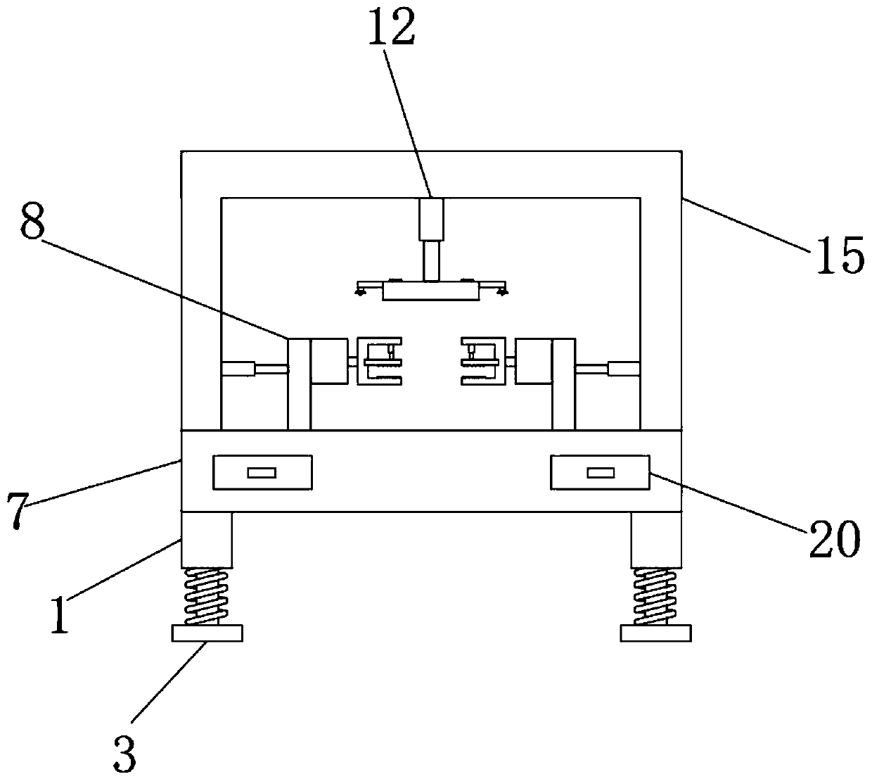
[0026] refer to Figure 1-3 , a fixing device for the processing of the middle plate of the automobile beam, including a workbench 7, the same gantry 15 is fixed by screws on both sides of the top outer wall of the workbench 7, and the inner wall on the opposite side of the gantry 15 is fixed by electric pushers. One end of the electric push rod piston rod is fixed with a sliding plate 8 by a screw, and the outer wall of the sliding plate 8 is fixed with a fixed block 10 by a screw, and the outer wall of one side of the fixed block 10 is provided with a mounting groove, and the inner wall of the mounting groove is fixed by a screw. The motor 9 is fixed, the output shaft of the motor 9 is connected with a U-shaped plate 16 through a coupling, and the top inner wall of the U-shaped plate 16 is fixed with a hydraulic rod 17 by screws, and one end of the piston rod of the hydraulic rod 17 is fixed with a fixed plate by screws 18.

[0027] In the present invention, the bottom inne...

Embodiment 2

[0034] refer to figure 1 , a fixing device for processing the middle plate of the automobile beam. Compared with Embodiment 1, this embodiment also includes that the outer walls on both sides of the mounting plate 11 are fixed with lamp panels 13 by screws, and the bottom outer walls of the lamp panels 13 are fixed by screws. There are illuminating lamps 14 .

[0035] The illuminating lamp 14 can play a good lighting effect, is convenient to turn on and use when the optical fiber is weak, and is convenient for workers to find the processing position.


PUM


Abstract

The invention discloses a fixing device for machining an automobile beam middle plate. The fixing device comprises a workbench, a portal frame is fixed to the two sides of the outer wall of the top ofthe workbench through screws, electric push rods are fixed to the inner walls of the opposite sides of the portal frame through screws, sliding plates are fixed to one ends of piston rods of the electric push rods through screws, fixing blocks are fixed to the outer walls of the sliding plates through screws, installation grooves are formed in the outer walls of one sides of the fixing blocks, motors are fixed to the inner walls of the installation grooves through screws, output shafts of the motors are connected with U-shaped plates through couplers, hydraulic rods are fixed to the inner walls of the tops of the U-shaped plates through screws, and fixing plates are fixed to one ends of piston rods of the hydraulic rods through screws. According to the fixing device, different surfaces ofthe middle plate can be machined conveniently, manual overturning is not needed, the operation is convenient, the machining efficiency is improved, the practicability is high, the machining positioncan be conveniently pinpointed by a worker, and the machining quality is improved.

Description

technical field [0001] The invention relates to the technical field of automobile production, in particular to a fixing device for processing a middle plate of an automobile frame. Background technique [0002] In the history of the world's automobile development, the domesticization of car consumption started with the development of economical cars. In most developed countries, economical cars are the mainstream of the family car market. Cars are favored by consumers, and the development of economical car industry is encouraged and supported by governments of various countries. [0003] With the increasing demand for cars in the market, more and more automobile manufacturers have appeared. In the automobile production process, the processing of the middle plate of the automobile frame is often involved. In the process of processing the middle plate of the automobile frame, often It needs to be fixed by a fixing device, and the existing fixing device needs to be manually tu...

Claims


Application Information

Patent Timeline
Patent Type & Authority Applications(China)
IPC IPC(8): B25H1/10F16F15/02F16F15/023F16F15/04
CPCB25H1/10F16F15/022F16F15/023F16F15/04F16F2222/12F16F2238/026
Inventor 高崇艳王靖罗姝鋆
Owner 十堰市乾德工贸有限公司
Why Eureka
Try Eureka