Fuel cell vehicle low-power-consumption multi-factor coupling heat radiation system and method

A heat dissipation system and fuel cell technology, applied in the direction of fuel cell heat exchange, fuel cells, fuel cell additives, etc., can solve problems such as energy loss and complex structure, and achieve the effect of effective heat utilization and maximum fan energy utilization

Inactive Publication Date: 2019-11-15
ZHONGTONG BUS HLDG
View PDF5 Cites 1 Cited by
  • Summary
  • Abstract
  • Description
  • Claims
  • Application Information

AI Technical Summary

Problems solved by technology

[0004] In order to overcome the deficiencies of the above-mentioned prior art, the present disclosure provides a fuel cell vehicle low-power multi-coupled cooling system and its working method, which solves the problems of complex structure and energy loss caused by separate heat dissipation in the existing cooling system, Balanced and effective use of energy

Method used


Image

  • Fuel cell vehicle low-power-consumption multi-factor coupling heat radiation system and method

Examples


Embodiment 1

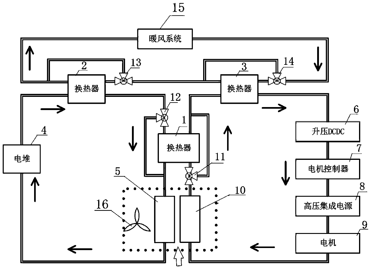
[0030] In order to overcome the complex structure of the existing heat dissipation system, the serious energy loss, and the lack of good utilization of the heat energy of the entire system, this embodiment provides a low-power multi-coupled heat dissipation system for fuel cell vehicles, which uses a single set of fans and double heat dissipation The heat exchanger structure replaces the original single fan and single radiator structure to maximize the energy utilization of the fan; by adding heat exchangers to the heat dissipation system of the electric stack cooling system and the cooling system of high-voltage components such as motors and motor controllers, the low temperature environment is realized. Use the heat of high-voltage components such as motors and motor controllers to preheat the stack; add heat exchangers between the cooling system of the stack, the cooling system of high-voltage components such as motors and motor controllers, and the heating system in the car ...

Embodiment 2

[0046] This embodiment provides a working method of a fuel cell vehicle low-power multi-coupled coupling cooling system. The method is implemented based on the fuel cell vehicle low-power multi-coupled cooling system described in Embodiment 1. The method includes the following steps:

[0047] S1, control the conduction of the first three-way solenoid valve 11 and the second three-way solenoid valve 12, the step-up DC / DC converter 6, the motor controller 7, the high-voltage integrated power supply 8 and the motor 9 are generated during the operation of the series connection The heat energy is input into the first heat exchanger 1 through the radiator, and the heat energy exchanged by the first heat exchanger 1 is transmitted to the fuel cell stack 4 through the radiator to preheat the fuel cell stack 4 .

[0048] S2, control the conduction of the third three-way solenoid valve 13 and the fourth three-way solenoid valve 14, the heat generated by the fuel cell stack 4 passes throu...

Embodiment 3

[0050] This embodiment provides an electric vehicle. The electric vehicle includes a fuel cell vehicle low-power multi-coupled cooling system and a warm air system. Heat exchange is performed between the fuel cell vehicle low-power multiple coupled cooling system and the warm air system.

[0051] For the specific structure of the fuel cell vehicle low-power multi-coupled cooling system of this embodiment, please refer to the relevant descriptions of the previous embodiments, and details are not repeated here.


PUM


Abstract

The invention discloses a fuel cell vehicle low-power-consumption multi-factor coupling heat radiation system and method. Problems of complicated structure, energy loss and the like, caused by singleheat radiation, of an existing heat radiation system are solved; and balanced effective utilization of energy is realized. The fuel cell vehicle low-power-consumption multi-factor coupling heat radiation system comprises an electric pile heat radiation system, a high voltage part heat radiation system, a first heat exchanger, a second heat exchanger and a third heat exchanger, wherein the first heat exchanger is correspondingly connected with the electric pile heat radiation system and the high voltage part heat radiation system, the second heat exchanger is connected between the electric pileheat radiation system and a heating system, and the third heat exchanger is connected between the high voltage part heat radiation system and the heating system.

Description

technical field [0001] The present disclosure relates to the technical field of thermal management of fuel cell vehicles, in particular to a low-power multi-coupled cooling system for fuel cell vehicles and a working method thereof. Background technique [0002] Existing heat dissipation systems perform heat exchange with the environment through radiators. Generally speaking, the two heat dissipation systems are independent, and no heat exchange is involved between the systems. The heat dissipation of the radiator can be realized by increasing the power of the fan, increasing the area of ​​the radiator and changing the arrangement position of the radiator. In addition, in traditional electric vehicles, the heater system is generally an electric heater, and there is no heat exchange between the cooling system and the heater system. [0003] During the research and development process, the inventors found that the existing cooling system has the disadvantages of complex stru...

Claims


Application Information

Patent Timeline
Patent Type & Authority Applications(China)
IPC IPC(8): B60H1/00B60H1/06B60L58/33B60L58/34H01M8/04007H01M8/04014
CPCB60H1/00271B60H1/00278B60H1/00392B60H1/06B60H2001/00307B60L58/33B60L58/34H01M8/04014H01M8/04074Y02E60/50Y02T10/72Y02T90/40
Inventor 范志先梁满志王丙虎冯海明张成良刘海慧
Owner ZHONGTONG BUS HLDG
Why Eureka
Try Eureka