High-speed braiding machine

A high-speed knitting machine and machine technology, applied in weft knitting, warp knitting, knitting and other directions, can solve the problems of inconvenient disassembly of the knitting machine runway groove, high accumulated error of parts, short service life, etc., and achieve increased rigidity and equipment performance. The effect of improved, high wear resistance

Active Publication Date: 2019-11-15
江苏响道精密机械有限公司
View PDF14 Cites 0 Cited by
  • Summary
  • Abstract
  • Description
  • Claims
  • Application Information

AI Technical Summary

Problems solved by technology

[0012] Existing knitting machine runway grooves are not easy to disassemble, and do not have a shaft sleeve, the steps of the rotor have many parts to accumulate high errors, the service life is short, and the production cost is high

Method used


Image

  • High-speed braiding machine
  • High-speed braiding machine
  • High-speed braiding machine

Examples


Embodiment 1

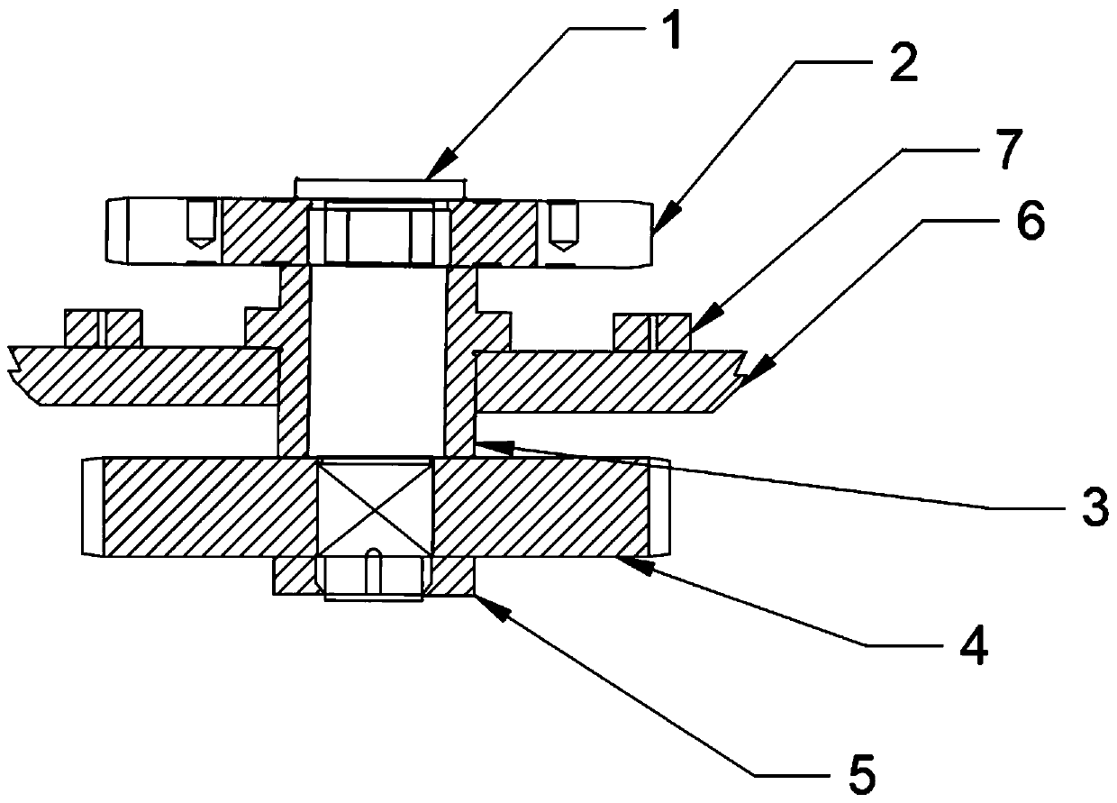
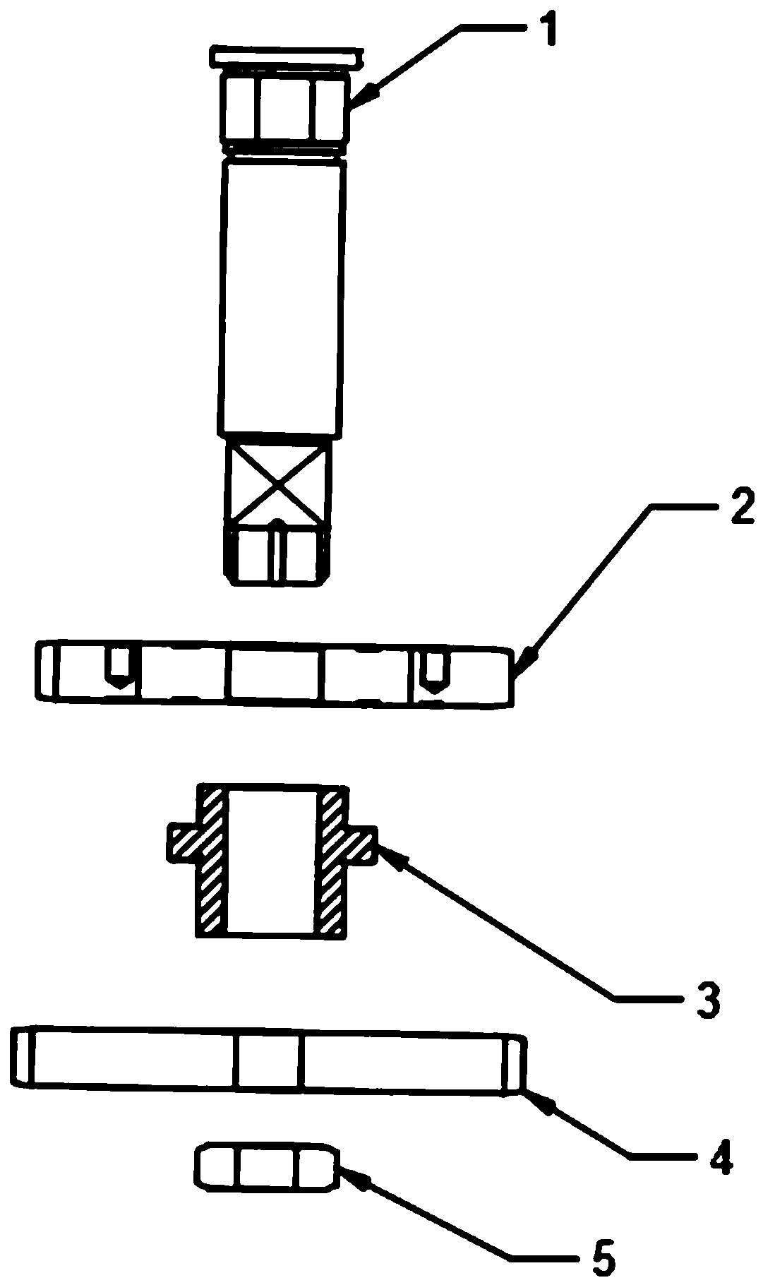
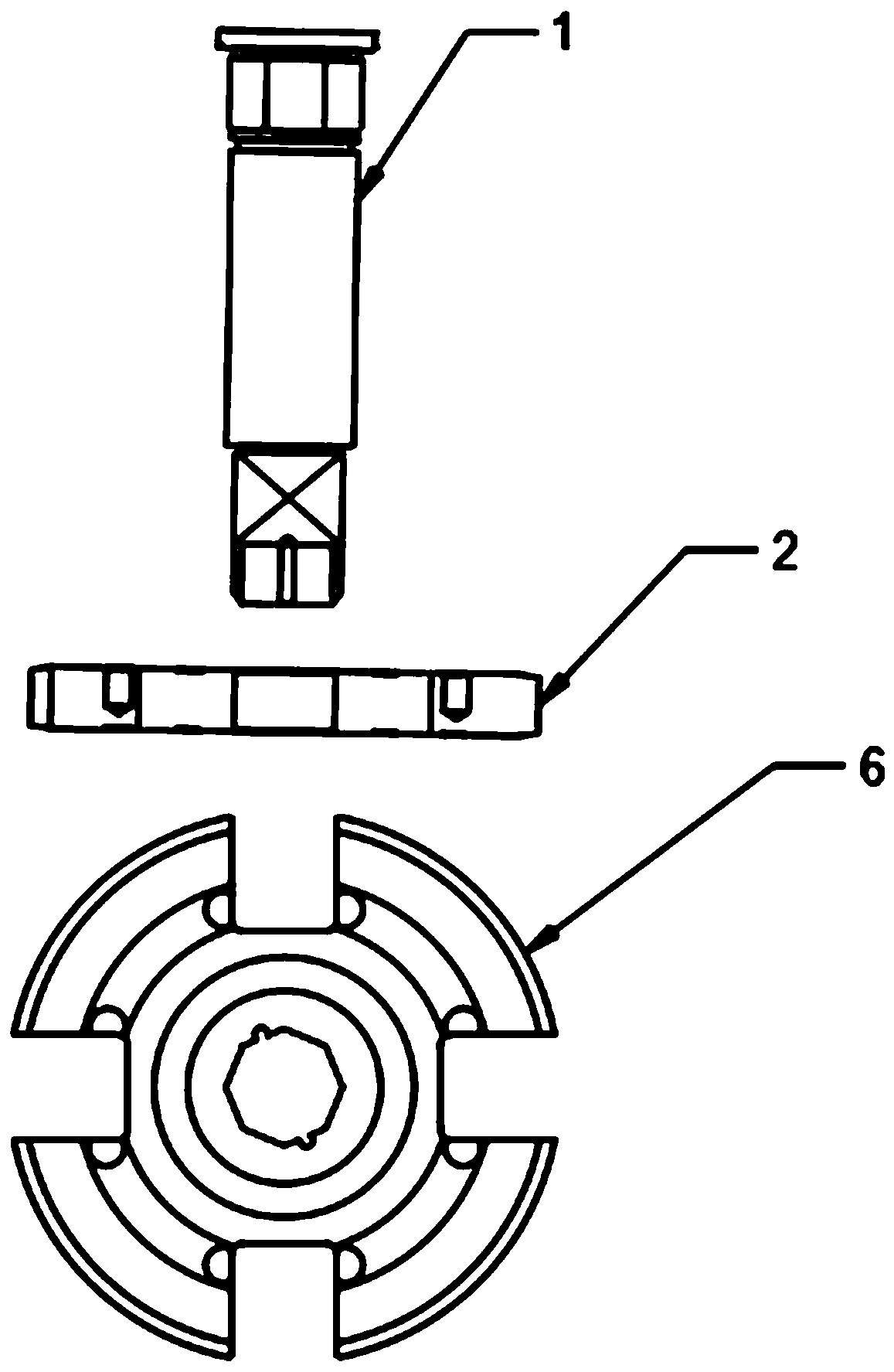
[0033] see Figure 1-Figure 9 , the present invention provides the following technical solutions: a high-speed braiding machine, including a rotor support shaft 1, a machine steel plate 6, the middle part of the machine steel plate 6 penetrates the rotor support sleeve 3, and the middle part of the rotor support sleeve 3 penetrates the rotor support shaft 1 The outer circumference of the rotor support shaft 1 is equipped with a combined rotor 2, the lower side of the machine steel plate 6 and the outer ring of the rotor support shaft 1 are equipped with a gear 4, and the outer ring of the rotor support shaft 1 and the lower side of the gear 4 are installed Have and tighten nut 5, the upper side of machine steel plate 6 is provided with runway groove 7, and the edge corner place of machine steel plate 6 is provided with support plate 11, and the rear side of support plate 11 is provided with oil groove 12.

[0034] In this embodiment: the outer ring 8 of the No. 1 runway, the o...


PUM


Abstract

The invention belongs to the technical field of textiles, and particularly relates to a high-speed braiding machine. The high-speed braiding machine comprises a rotor supporting shaft and a machine steel plate, wherein a rotor supporting shaft sleeve penetrates through the middle of the machine steel plate, the rotor supporting shaft penetrates through the middle of the rotor supporting shaft sleeve, the periphery of the rotor supporting shaft is provided with combined rotors, and the lower side of the machine steel plate and the outer ring of the rotor supporting shaft are provided with gears. An arranged first runway outer ring, a second runway outer ring and a runway inner ring can be spliced into a whole runway and can be spliced into runways of different sizes according to needs, theuse efficiency is high, runway groove assemblies are produced in batches by utilizing a powder metallurgy process mould, the precision is high, the consistency is good, the production efficiency is high, the production cost is reduced, each runway groove assembly is assembled on an intermediate plate, the situation is cancelled that an annular groove and a runway groove crossing block need to be machined for a whole original panel, the high-speed braiding machine runs more smoothly compared with a traditional machine, reversing is sensitive, the power loss is reduced, and energy saving and high efficiency are further achieved.

Description

technical field [0001] The invention belongs to the technical field of textiles, and in particular relates to a high-speed knitting machine. Background technique [0002] Weaving is roughly divided into two processes: spinning and weaving. According to legend, the origin of Chinese weaving began with Lei Zu raising silkworms and smelting silk. Archeology found bone needles on the archaeological site of the Upper Cave Man in the Paleolithic Age. It is the earliest known weaving. Origin: In the Neolithic Age, the spinning wheel was invented, which made silk smelting more convenient. In the Western Zhou Dynasty, primitive textile machines appeared: the spinning wheel and the wheel. The Jacquard loom was invented in the Han Dynasty. Technology is programmed into it. [0003] The original meaning of textile is taken from the general term of spinning and weaving, but with the continuous development and improvement of the textile knowledge system and subject system, especially aft...

Claims


Application Information

Patent Timeline
Patent Type & Authority Applications(China)
IPC IPC(8): D04B15/00D04B27/00D04B35/00
CPCD04B15/00D04B27/00D04B35/00
Inventor 于增伟
Owner 江苏响道精密机械有限公司
Why Eureka
Try Eureka