Eureka AIR delivers breakthrough ideas for toughest innovation challenges, trusted by R&D personnel around the world.

Light emitting unit, light emitting device and distance measuring device

A light emission unit and emission device technology, which is applied in measuring devices, optical components, optics, etc., can solve the problems of limited detection distance of distance measuring equipment and low luminous power of light sources

Inactive Publication Date: 2019-11-15
SHENZHEN ORBBEC CO LTD
View PDF15 Cites 3 Cited by
  • Summary
  • Abstract
  • Description
  • Claims
  • Application Information

AI Technical Summary

Problems solved by technology

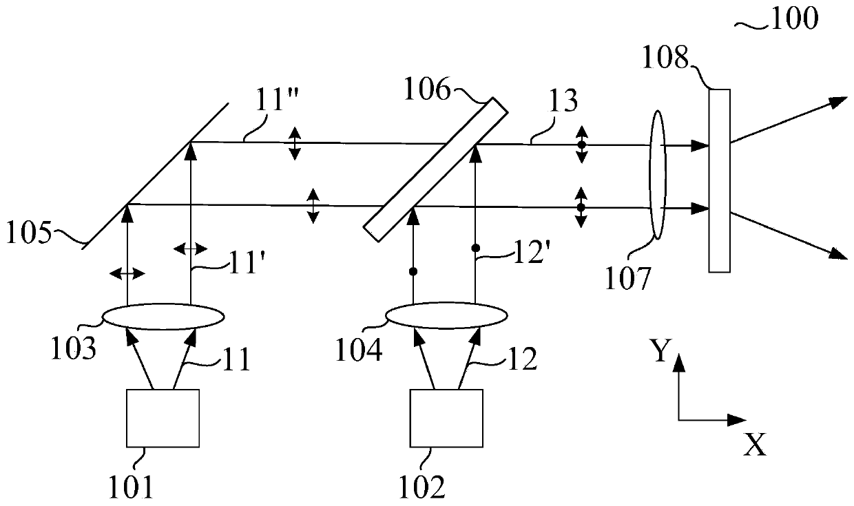
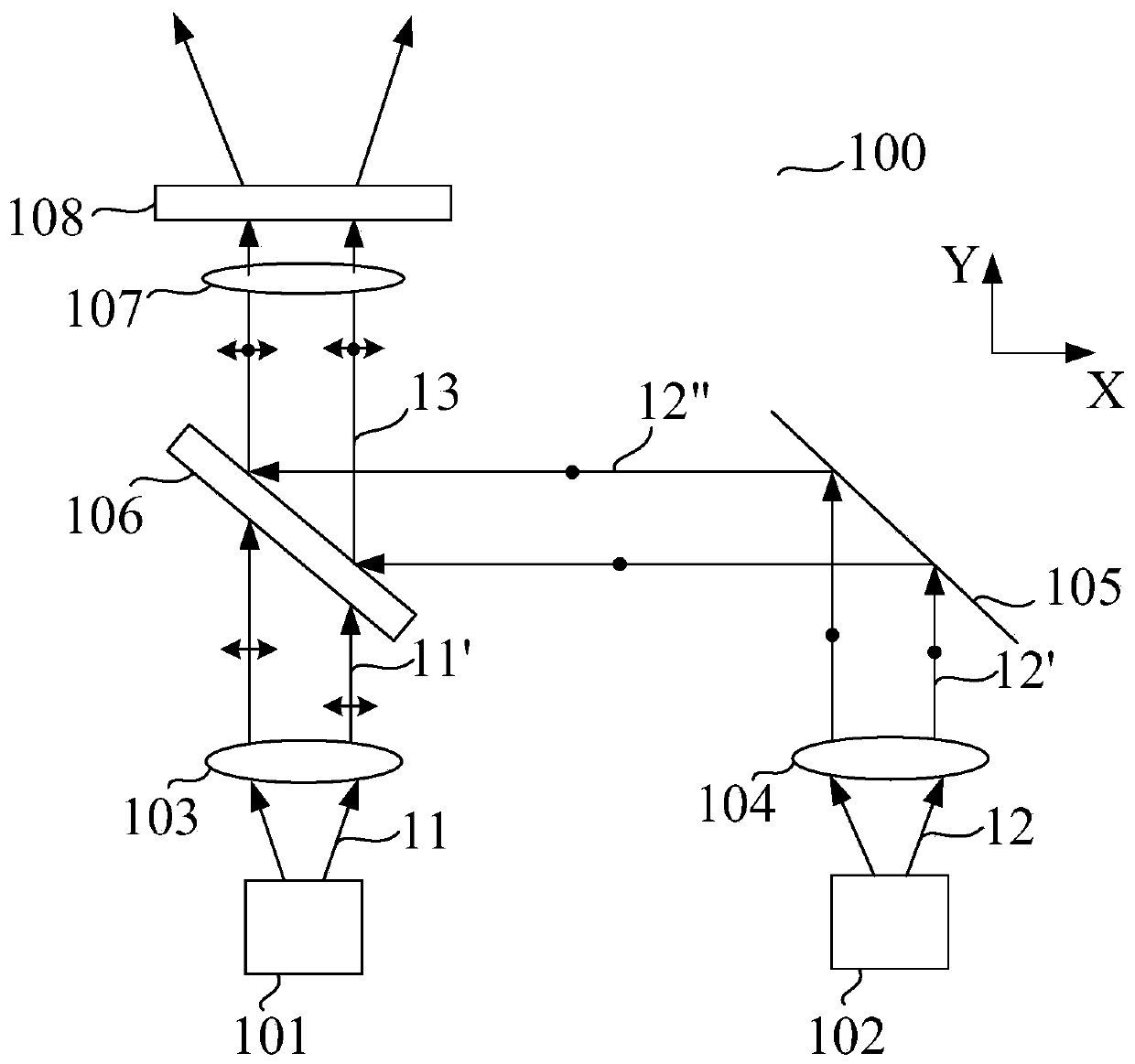
[0004] The purpose of the present invention is to overcome the shortcomings of the above-mentioned prior art, and to provide a light emitting unit, which aims to solve the problem that the light source of the existing light emitting device has a low luminous power, and thus the detection distance of the distance measuring device is limited

Method used


Image

  • Light emitting unit, light emitting device and distance measuring device
  • Light emitting unit, light emitting device and distance measuring device
  • Light emitting unit, light emitting device and distance measuring device

Examples


Embodiment Construction

[0035] In order to make the object, technical solution and advantages of the present invention clearer, the present invention will be further described in detail below in conjunction with the accompanying drawings and embodiments. It should be understood that the specific embodiments described here are only used to explain the present invention, not to limit the present invention.

[0036] It should be noted that when an element is referred to as being “fixed” or “disposed on” another element, it may be directly on the other element or be indirectly on the other element. When an element is referred to as being "connected to" another element, it can be directly connected to the other element or indirectly connected to the other element.

[0037] It should also be noted that the orientation terms such as left, right, up and down in the embodiments of the present invention are only relative concepts or refer to the normal use state of the product, and should not be regarded as re...


PUM


Abstract

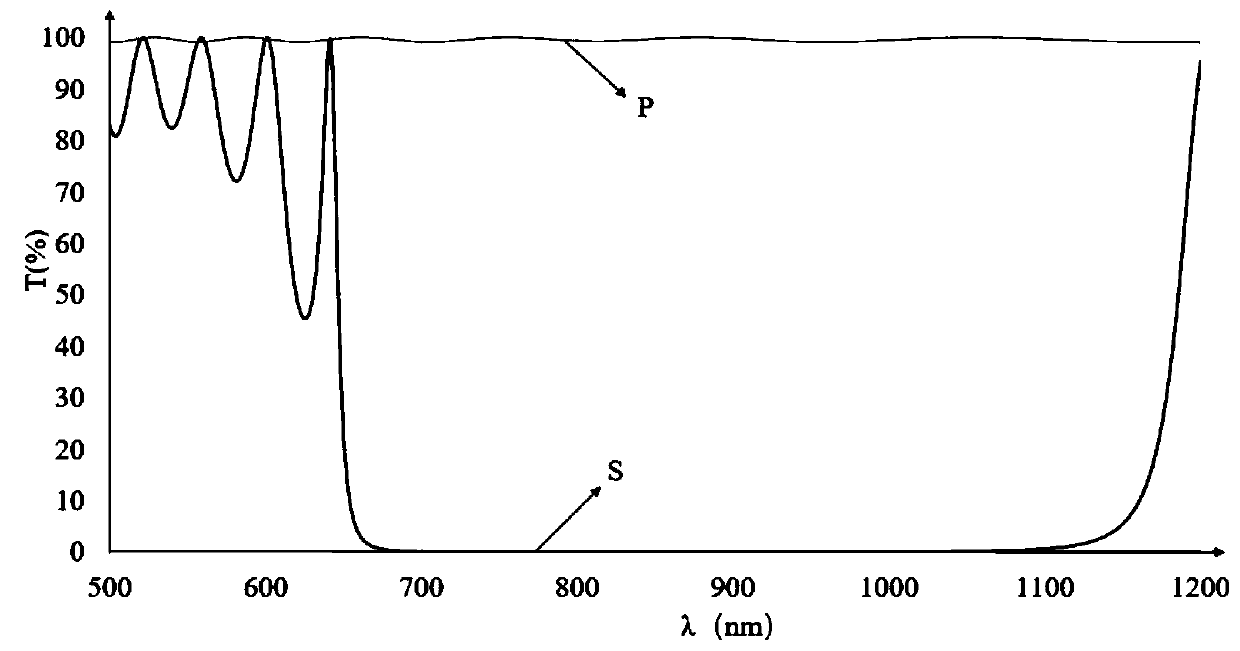
The invention provides a light emitting unit, a light emitting device and a distance measuring device. The light emitting unit comprises a light emitting assembly, a reflecting mirror, and polarizingbeam splitters. The light emitting assembly consists of a first light emitting terminal for emitting first polarized light and a second light emitting terminal for emitting second polarized light, wherein the two light emitting terminals have the optical axes arranged in parallel; and the first polarized light and the second polarized light have the parallel emitting directions and vibration directions perpendicular to each other. The reflecting mirror is arranged at the propagation path of the first polarized light and is aligned with the first light emitting terminal. The polarizing beam splitters are arranged at the propagation paths of the first polarized light and the second polarized light and are opposite to the second light emitting terminal. The first polarized light and the second polarized light enter the polarizing beam splitters at brewster angles; and the second polarized light reflected by the polarizing beam splitters is combined with the first polarized light completely transmitted through thepolarizing beam splitter to form one beam of integrated light. Therefore, the light emitting power of the light source of the light emitting device can be improved; and thus the detection distance of the distance measuring device is increased.

Description

technical field [0001] The invention belongs to the field of optical distance measuring equipment, and in particular relates to a light emitting unit, a light emitting device and distance measuring equipment. Background technique [0002] At present, the ranging technologies of common optical ranging devices on the market usually include structured light, TOF (Time Of Flight, time-of-flight ranging method), laser radar, etc. After the signal reflected from the object to be measured is properly processed, the relevant information of the object to be measured can be obtained, so as to realize the detection, tracking and identification of the object to be measured. [0003] However, during the detection process of the ranging equipment, the luminous power of the light source will directly affect the detection distance of the ranging equipment, that is, the detection distance of the existing ranging equipment is limited by the luminous power of the light source. The scheme of e...

Claims


Application Information

Patent Timeline
IPC IPC(8): G01S7/481G01S17/08G01S17/10G01S7/484G01S7/486G02B27/28G02B26/10
CPCG01S7/4816G01S7/4815G01S7/4817G01S17/08G01S17/10G01S7/484G01S7/486G02B27/283G02B26/105
Inventor 黄杰凡
Owner SHENZHEN ORBBEC CO LTD
Why Eureka
Eureka Blog
Learn More