
Non-thermal candoluminescence for generating electricity

A photoluminescent material and electric energy technology, applied in photovoltaic power generation, luminescent materials, photovoltaic modules, etc., can solve problems such as heat loss without consideration

Inactive Publication Date: 2019-11-15
TECHNION RES & DEV FOUND LTD
View PDF6 Cites 2 Cited by
  • Summary
  • Abstract
  • Description
  • Claims
  • Application Information

AI Technical Summary

Problems solved by technology

However, this does not take into account other heat losses

Method used


Image

  • Non-thermal candoluminescence for generating electricity
  • Non-thermal candoluminescence for generating electricity
  • Non-thermal candoluminescence for generating electricity

Examples


Embodiment Construction

[0053] foreword

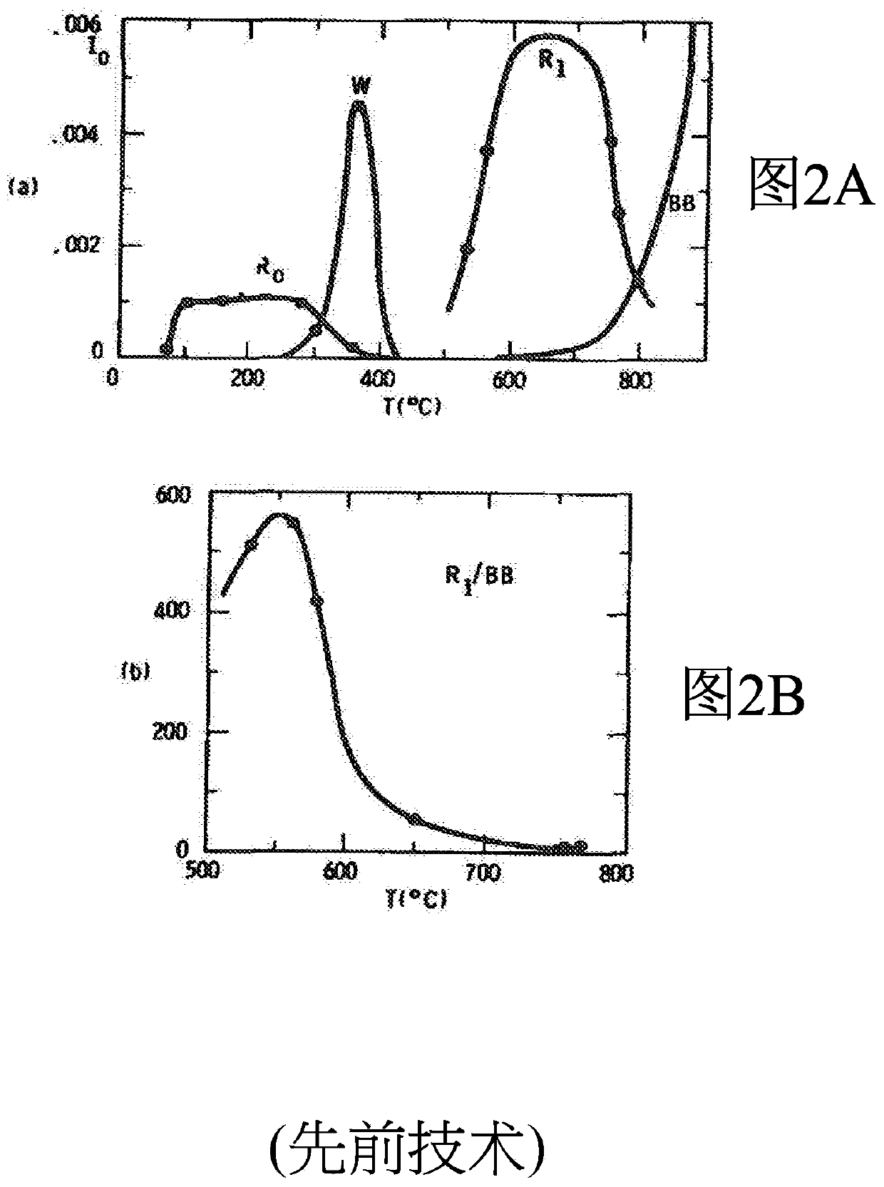
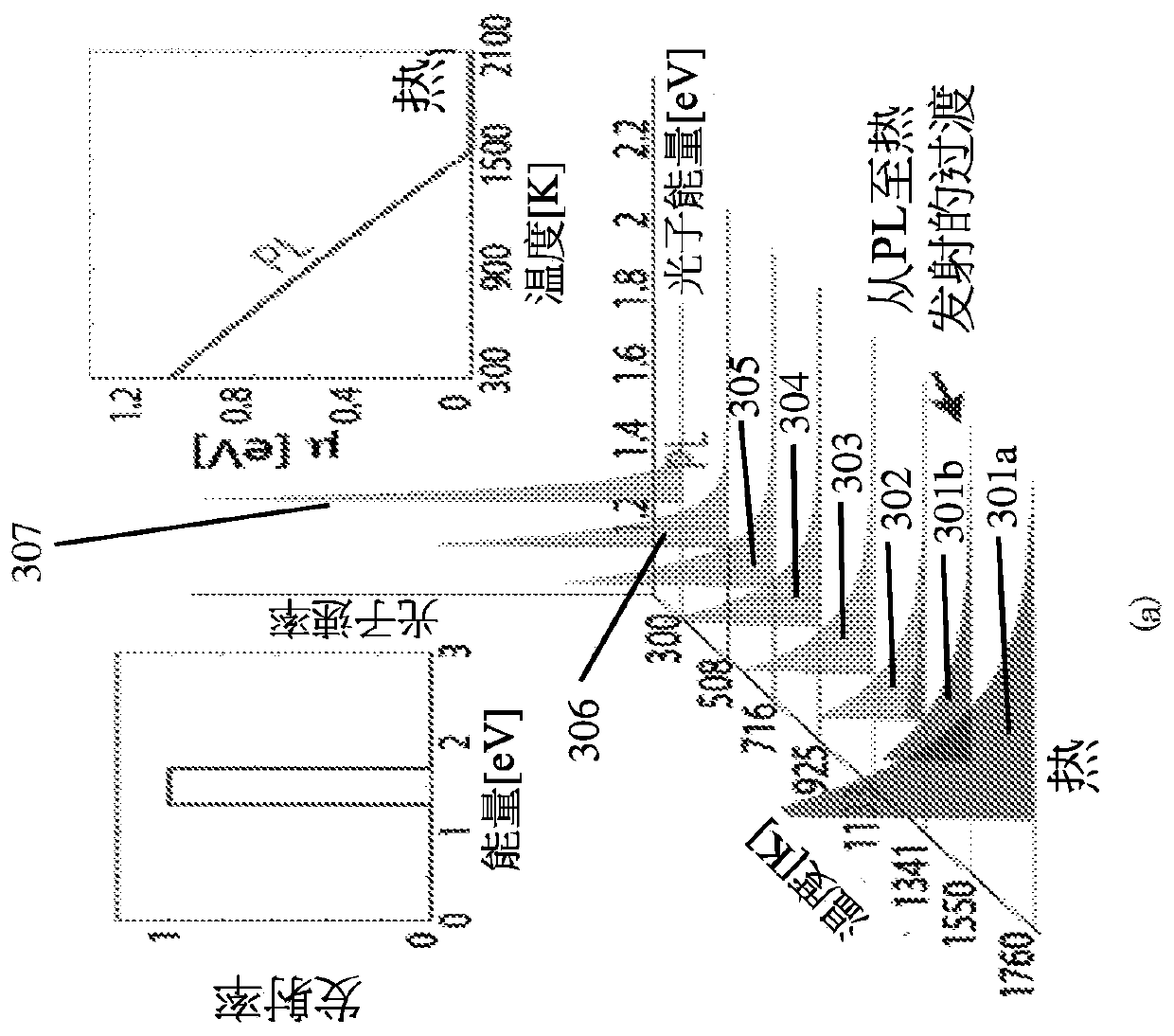
[0054] The inventors found that, in contrast to thermal emission, the rate of non-thermal radiation (NTR) is conserved with increasing temperature, while each photon is blueshifted. As used herein, "blue shift" is any decrease in wavelength and corresponding increase in frequency of an electromagnetic wave. A further increase in temperature results in an abrupt transition to thermal emission, where the photon rate increases dramatically.

[0055] The underlying physics governing the interaction between NTR and thermal emission is expressed by the generalized Planck's law via Equation 1 (Eq. 1), as follows:

[0056]

[0057] where R is the emitted photon flux (number of photons per second per unit area). Here, T is the temperature, ε is the emissivity, is the photon energy, K b is Boltzmann's constant and μ is the chemical potential. The corresponding emission energy rate is given by definition. The chemical potential μ > 0 defines a temperature ...


PUM


Abstract

Methods and systems convert combustion products to electricity, by efficiently coupling between photovoltaic cells with photons. The photons are emitted from a burning process of a photoluminescence material, the burning process including the chemical reaction of combustion.

Description

[0001] related application [0002] This patent application is related to and claims priority to co-owned U.S. Provisional Patent Application Serial No. 62 / 480459 (Title: Athermal Thermoluminescence for Power Generation), filed April 2, 2017, the disclosure of which is incorporated by reference The contents of which are incorporated herein in their entirety. technical field [0003] The present invention relates to a method and system for converting various combustion products into electricity. Background technique [0004] Thermoluminescence (candoluminescence) is the emission of light by certain materials at high temperatures, usually by exposure to a flame. The intensity of the light at some wavelengths may be higher than the black body emission expected from incandescence at the same temperature. A "black body" as discussed herein is an object that absorbs all radiation falling on it at all wavelengths. When a blackbody is at a uniform temperature, its emission has a...

Claims


Application Information

Patent Timeline
Patent Type & Authority Applications(China)
IPC IPC(8): H02S10/30F23D99/00
CPCF23D99/00H02S10/30Y02E10/50C09K11/0822C09K11/59C09K11/62C09K11/661C09K11/68C09K11/7407
Inventor 卡梅尔·罗茨柴尔德
Owner TECHNION RES & DEV FOUND LTD
Learn More