

Frame type steam rice cooker
A steam and rice cooker technology, which is applied in the directions of steam cooking utensils, cooking utensils lids, and the structure of cooking utensils, etc., can solve the problem of uneven heating, and achieve the effects of uniform heating and high thermal efficiency.
- Summary
- Abstract
- Description
- Claims
- Application Information
AI Technical Summary
Problems solved by technology
Method used
Image

Examples
Embodiment 1
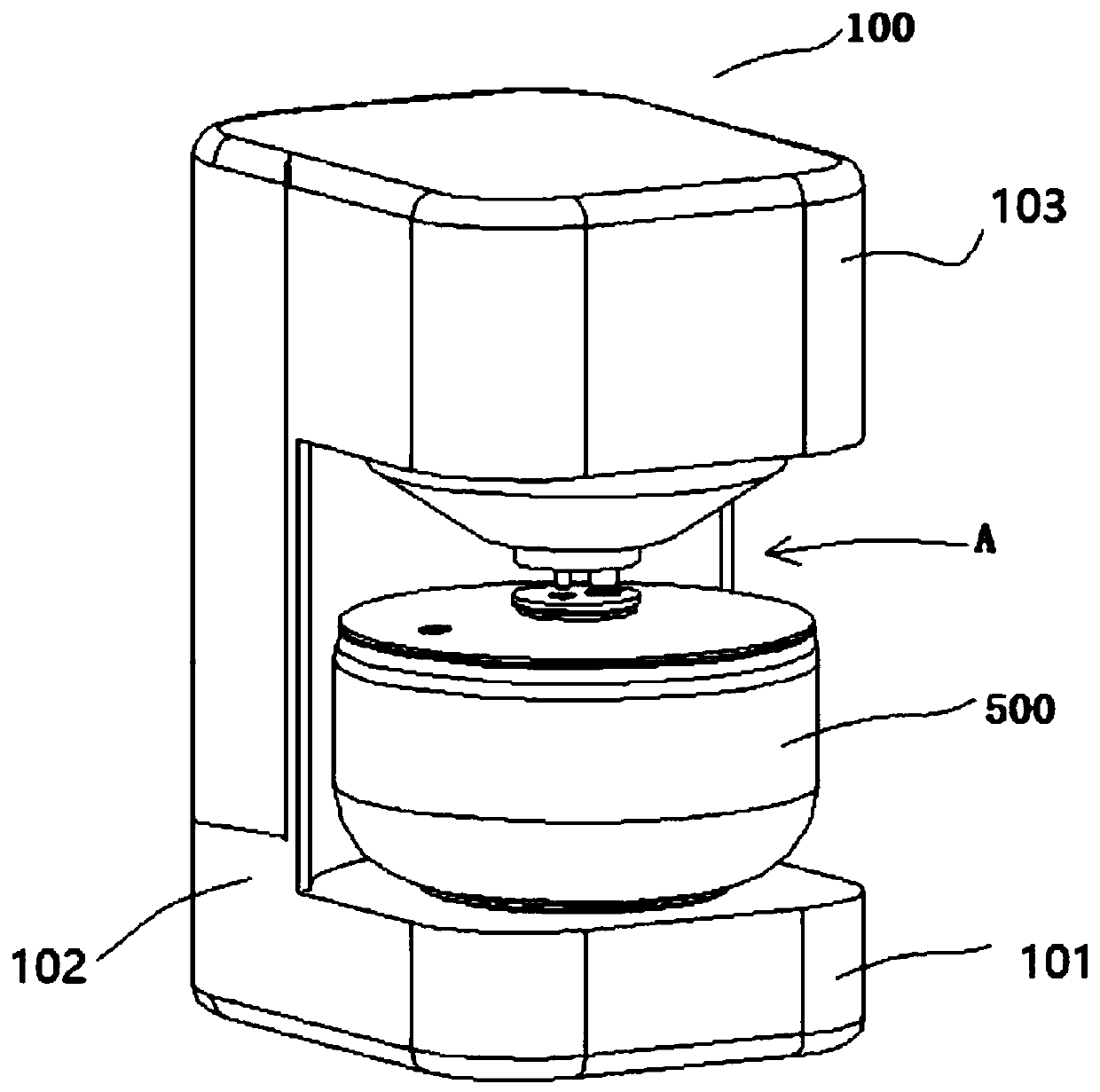
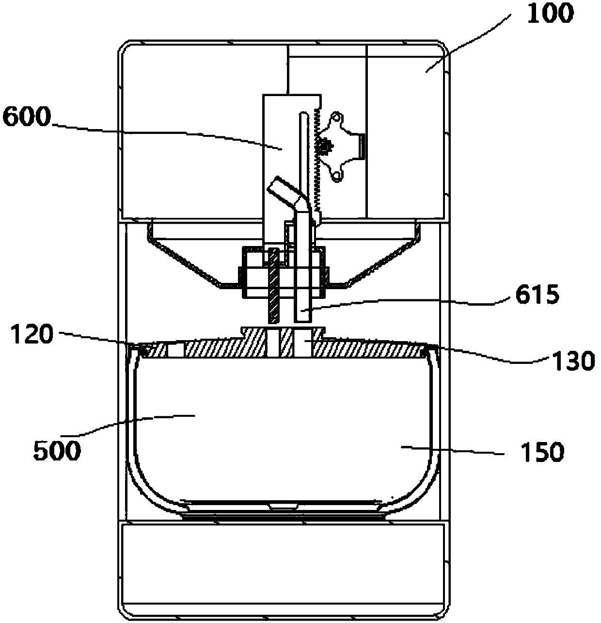
[0057] refer to figure 1 , a frame-type steam rice cooker, comprising a pot liner 500 and a frame body 100, the frame body 100 includes a bearing portion 101, a support portion 102 formed by extending upward from the carrying portion 101, and a support portion 102 extending upward from the support portion 102 to the top of the pot liner 500 The top 103, the top 103 and the bearing part 101 form an open space A for taking and placing the pot, such as figure 2 As shown, the support portion 102 or the top 103 is provided with a steam generator 600 for introducing steam into the inner pot 500 for cooking. There is a pot cover 120 that can be covered on the pot liner 500, and the pot liner 500 and the pot cover 120 form a cooking cavity 150;
[0058] In this embodiment, it is mainly aimed at the cooking of rice. Of course, in some modified embodiments of this embodiment, it should be understood that it should not be limited to the ingredients shown in this embodiment and the acco...
Embodiment 2
[0074] The difference between this embodiment and Embodiment 1 is that, if Figure 32 As shown, the pot liner 500 is in the form of a double pot; specifically:
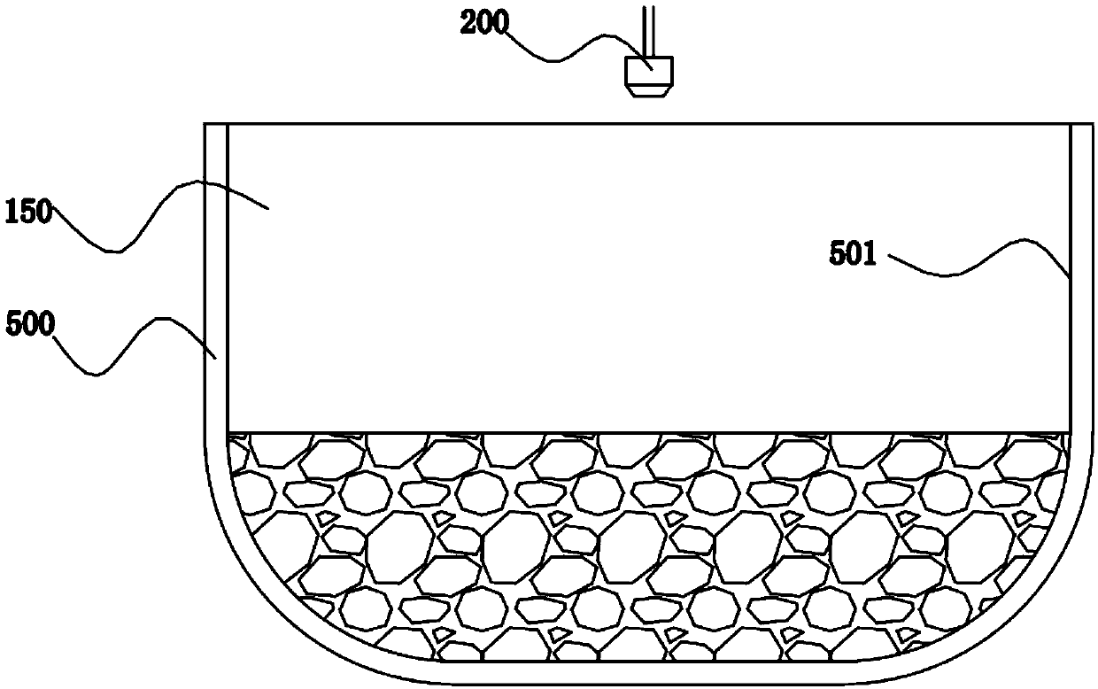
[0075] Such as Figure 33 As shown, the inner pot includes a first steam passage 531 formed on one side of the outer wall 502 of the inner pot 500, and a second steam passage 532 above the inner pot 500. The first steam passage 531 and the cooking cavity 150 pass through the first steam passage 531. The two steam passages 532 are connected, and the tumbling steam flow in the cooking cavity 150 cuts into the first steam passage 531 along the direction of the second steam passage 532 toward the outer wall 502 .
[0076] This embodiment is intended to solve the technical problem that the outer wall of the inner pot cannot be heated in the first embodiment. In the first embodiment, the steam flow of the nozzle is directed into the cooking cavity 150, and when the inner wall 501 of the inner pot and the heating of the ing...
PUM
 Abstract
Description
Claims
Application Information