Water power fire-fighting robot

A fire-fighting robot and water-powered technology, applied in fire rescue and other directions, can solve the problems of explosion fueling fire, potential safety hazards, poor fire-fighting effect, etc., and achieve the effect of wide-ranging fire-fighting

Active Publication Date: 2019-11-19
JIANGSU TAIYANG FIRE EQUIP
View PDF9 Cites 0 Cited by
  • Summary
  • Abstract
  • Description
  • Claims
  • Application Information

AI Technical Summary

Problems solved by technology

[0002] With the continuous development of society, the urbanization process is accelerating, and urban construction is becoming more and more intensive. However, while the city brings convenience to people, it also brings many safety hazards, and the traditional outdoor fire extinguishing devices for dense buildings cannot Go deep into the floor to extinguish the fire, resulting in poor fire extinguishing effect. For areas with large fires, the human body cannot approach and can only use robots to bring people manpower. However, the existing fire-fighting robots are mostly driven by electric motors and diesel engines. Both need to carry batteries or fuel. There is a risk of an explosion fueling a fire and urgent changes are needed

Method used


Image

  • Water power fire-fighting robot
  • Water power fire-fighting robot
  • Water power fire-fighting robot

Examples


Embodiment 1

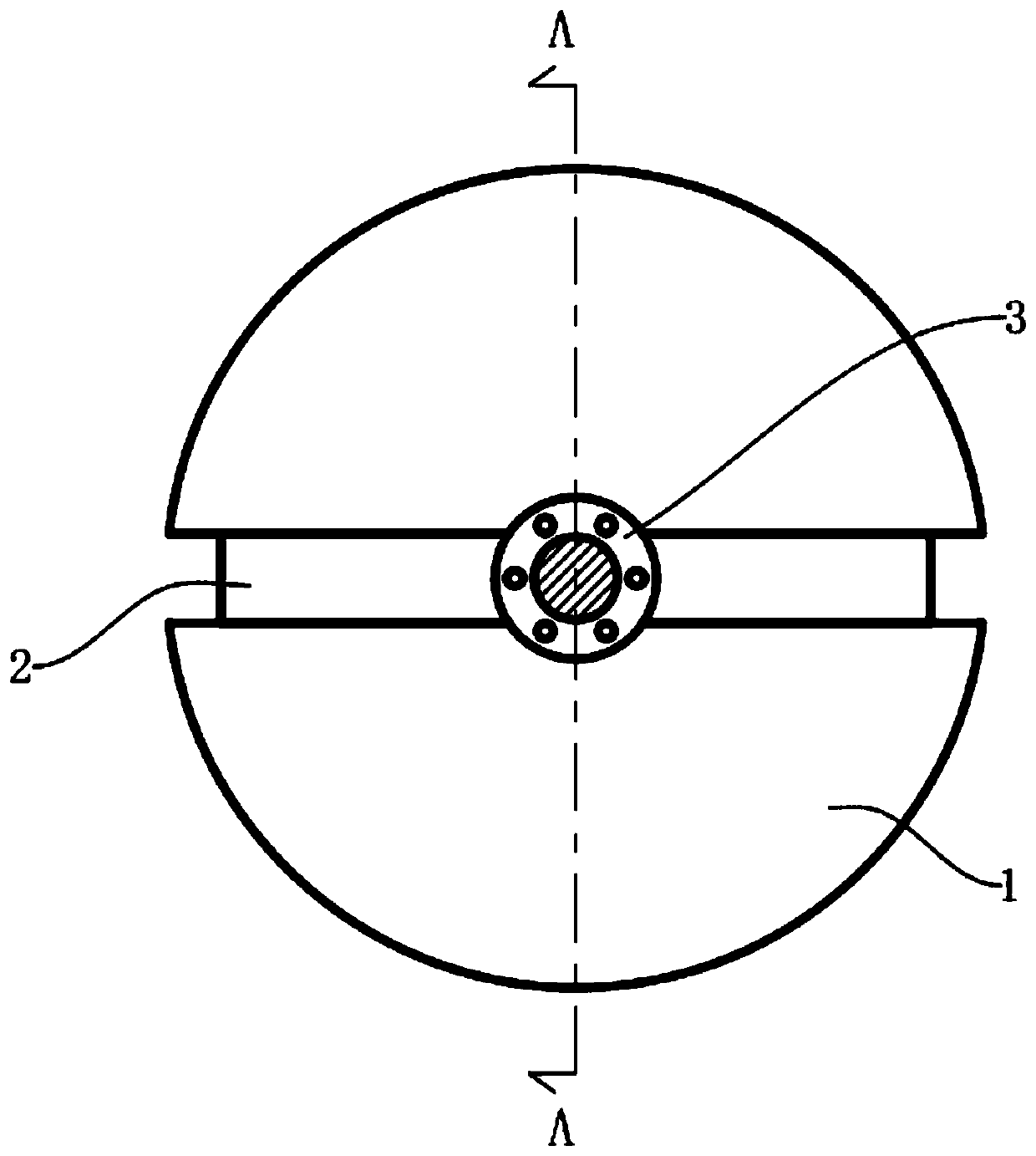
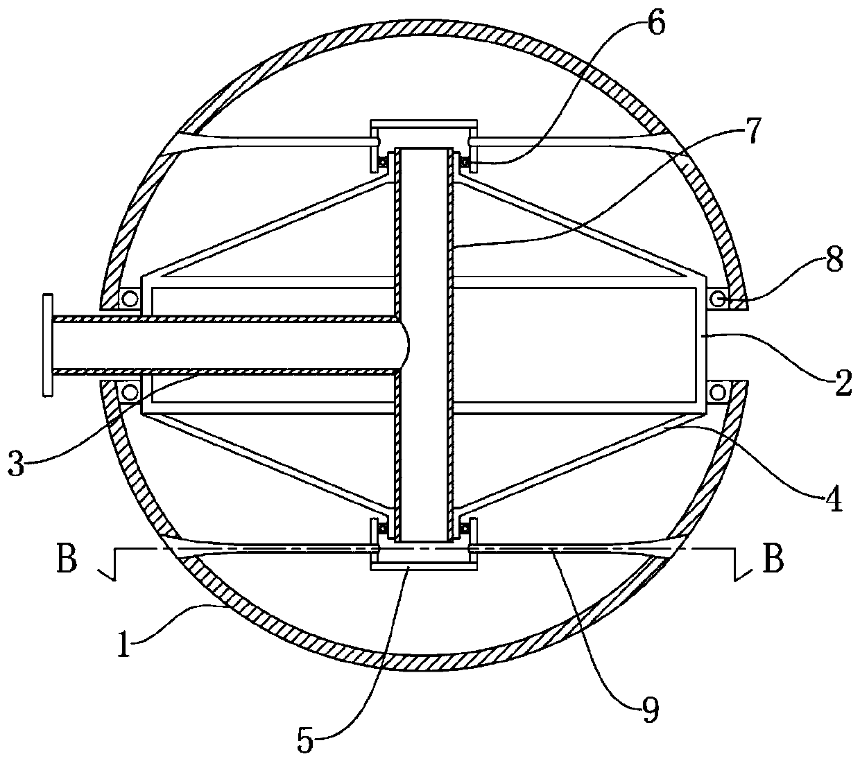
[0021] refer to Figure 1 to Figure 3 The upper and lower sides of the frame 2 are provided with hemispheres 1, and the inner surfaces of the two hemispheres 1 are connected to the frame 2 in rotation.

[0022] The skeleton 2 adopts a cylindrical structure, and the upper and lower sides of the skeleton 2 are interference-fitted with the second bearing 8, the skeleton 2 is fixedly connected with the hemisphere 1 through the second bearing 8, and the function of the second bearing 8 is to make the hemisphere 1 It rotates relative to the frame 2, so that the upper and lower hemispheres 1 can rotate independently, which greatly avoids the entanglement of the pipes connected to the water inlet pipe 3 caused by the rotation of the frame 2.

[0023] In a preferred embodiment of the present invention, both the hemisphere 1 and the frame 2 are made of metal.

[0024] The skeleton 2 is fixedly connected with a water inlet pipe 3 and a shunt pipe 7, and the two form a three-way structur...

Embodiment 2

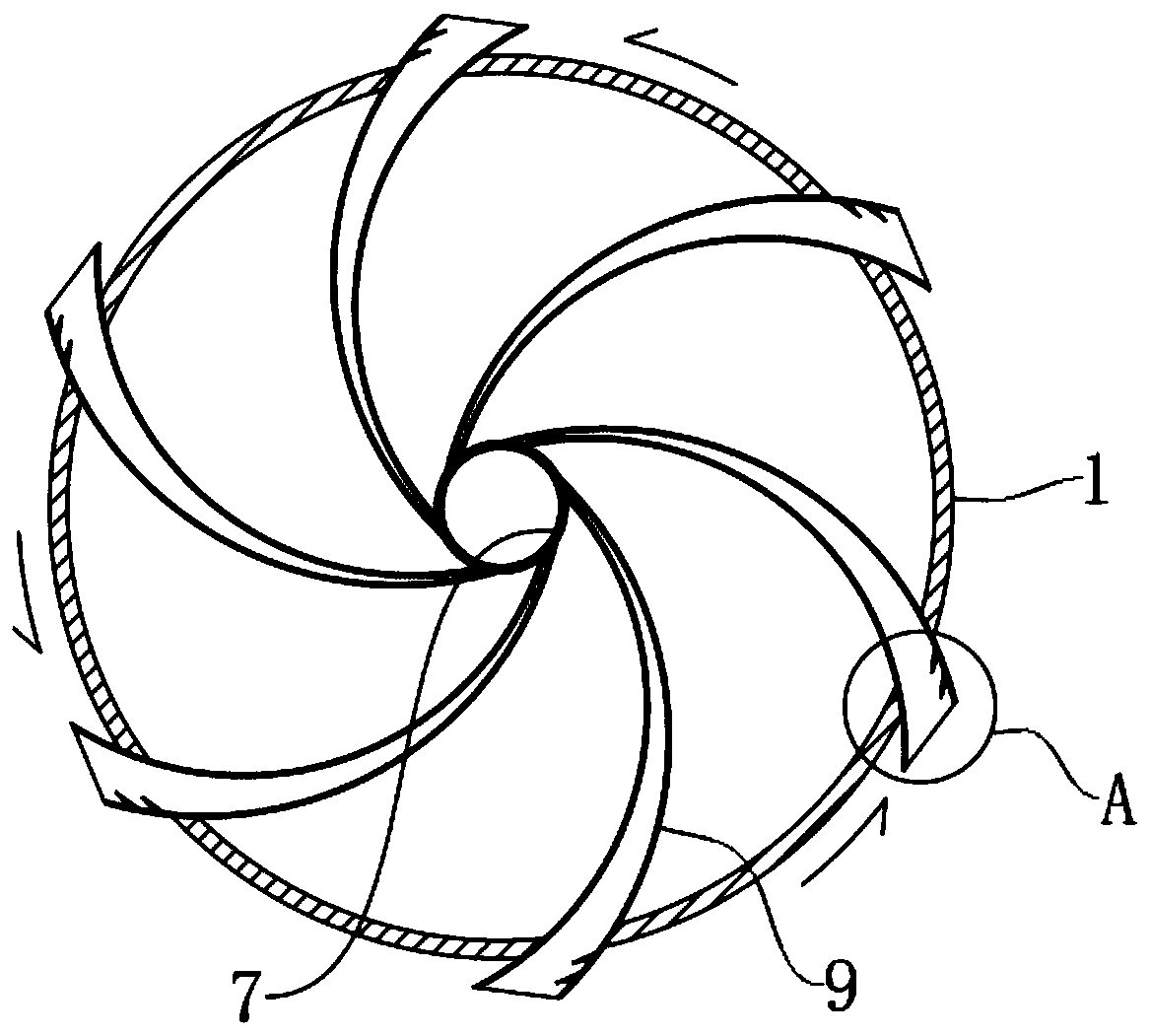
[0028] refer to image 3 and Figure 4 , this embodiment is further set as follows on the basis of Embodiment 1:

[0029] A side of the spray pipe 9 close to the outlet is fixedly connected with a plurality of baffles 11 inclined toward the outlet, and a through hole 12 is opened between two adjacent baffles 11 .

[0030] Compared with the first embodiment, this embodiment is more energy-saving, according to the "Bernoulli effect": the faster the flow rate, the lower the pressure. Therefore, when the liquid in the injection pipe 9 passes through quickly, a negative pressure can be formed in the injection pipe 9, so that the outside air enters the injection pipe 9 through the through hole 12, so that the original pure liquid injection becomes a solid-liquid two-phase injection , thereby saving water resources. And the setting of baffle plate 11 makes liquid flow along the inclined-plane of baffle plate 11 to increase the flow velocity at this place and increase the pumping p...


PUM


Abstract

The invention discloses a water power fire-fighting robot, and relates to the technical field of fire-fighting equipment. The water power fire-fighting robot comprises a framework, and the upper sideand the lower side of the framework are sleeved with hemispheres. The inner surfaces of the two hemispheres are rotationally connected with the framework. The framework is fixedly connected with a water inlet pipe and a flow dividing pipe, and a tee joint structure is formed by the water inlet pipe and the flow dividing pipe. The two ends of the flow dividing pipe are rotationally connected with sleeves. The sleeves communicate with multiple spraying pipes at equal intervals in the circumferential direction. The ends, away from the sleeves, of the spraying pipes penetrate through the hemispheres and communicate with the external space. According to the water power fire-fighting robot, batteries or fuel or other energy sources with hidden explosion danger do not need to serve as power, andsafety and reliability are achieved; and meanwhile the surface of the water power fire-fighting robot is approximately spherical, and the water power fire-fighting robot can go deep into a complex environment, saves energy and is wide in fire extinguishing range.

Description

technical field [0001] The invention relates to the technical field of fire-fighting equipment, in particular to a hydrodynamic fire-fighting robot. Background technique [0002] With the continuous development of society, the urbanization process is accelerating, and urban construction is becoming more and more intensive. However, while the city brings convenience to people, it also brings many safety hazards, and the traditional outdoor fire extinguishing devices for dense buildings cannot Go deep into the floor to extinguish the fire, resulting in poor fire extinguishing effect. For areas with large fires, the human body cannot approach and can only use robots to bring people manpower. However, the existing fire-fighting robots are mostly driven by electric motors and diesel engines. Both need to carry batteries or fuel. There is a risk of an explosion fueling a fire, and urgent change is needed. Contents of the invention [0003] The purpose of the present invention i...

Claims


Application Information

Patent Timeline
Patent Type & Authority Applications(China)
IPC IPC(8): A62C27/00A62C31/02
CPCA62C27/00A62C31/02
Inventor 倪爱琴
Owner JIANGSU TAIYANG FIRE EQUIP
Why Eureka
Try Eureka