Shipborne repairing equipment for large-size river and lake polluted water repairing
A water quality, large-scale technology, applied in water/sewage treatment equipment, polluted waterway/lake/pond/river treatment, special-purpose ships, etc. Problems, to achieve the effect of easy repair and avoid death
- Summary
- Abstract
- Description
- Claims
- Application Information
AI Technical Summary
Problems solved by technology
Method used
Image

Examples
Embodiment
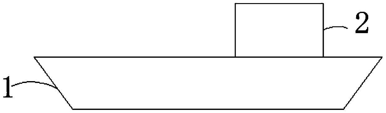
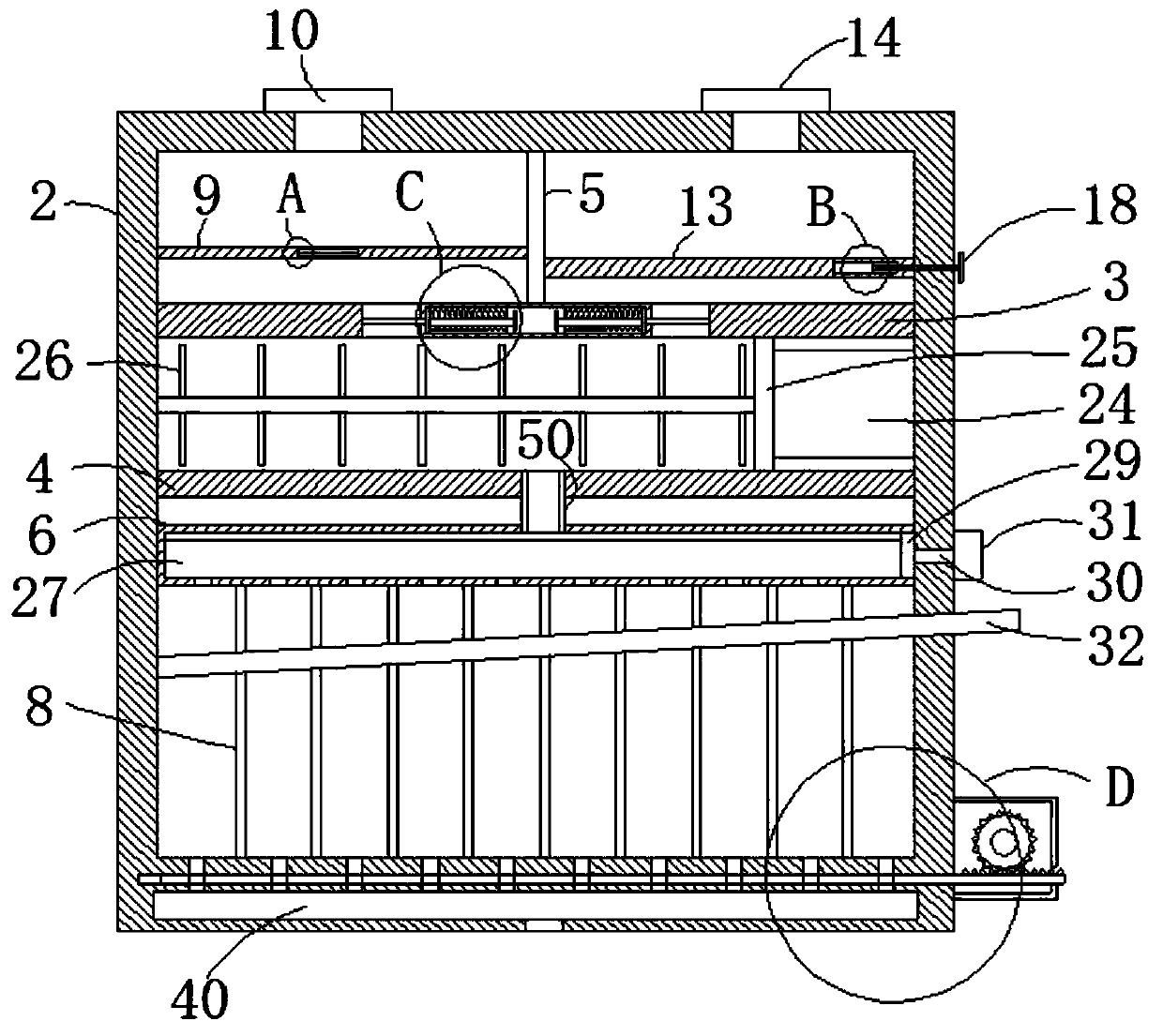
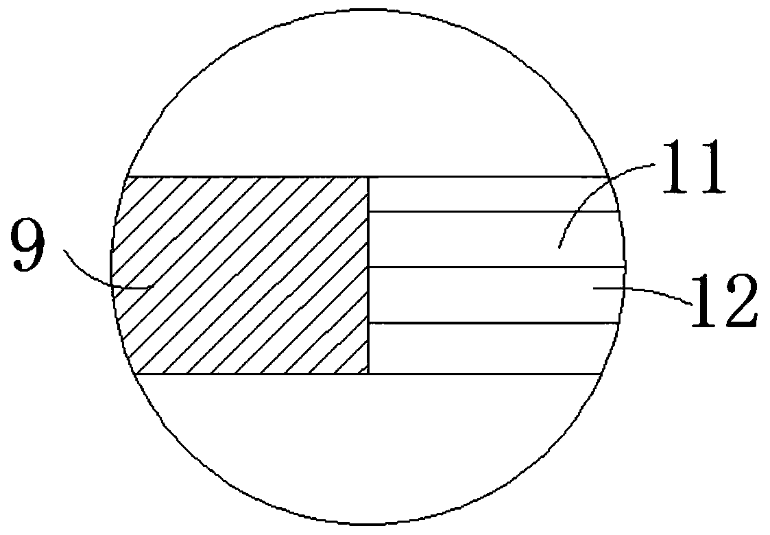
[0025] Such as Figure 1-8 As shown in the figure, a ship-mounted repairing equipment used for repairing the polluted water quality of large rivers and lakes includes a hull 1, the upper end of the hull 1 is fixedly connected with a treatment box 2, and the inner side wall of the treatment box 2 is fixedly connected with a first transverse plate 3 and a second horizontal plate 3. Two horizontal plates 4, the inside of the processing box 2 is divided into a storage room, a batching room and a breeding room from top to bottom by the first horizontal plate 3 and the second horizontal plate 4, and the side wall of the material storage room is fixedly connected with a vertical plate 5. The material storage room is divided into a first storage mechanism for containing nutrient solution and a second storage mechanism for containing clean water by the vertical plate 5. On the side wall of the first horizontal plate 3, there are corresponding The positions are all provided with a mater...
PUM
 Abstract
Description
Claims
Application Information
PatSnap Eureka turns technology decisions into work you can execute. Powered by our Innovation Knowledge Graph, it runs expert workflows across engineering, life sciences, materials and intellectual property. Get your review-ready output in minutes.


