
An integrated structure and construction method of assembly and pouring combination of subway underground excavation station

A technology that integrates structures and construction methods, applied in shaft equipment, earthwork drilling, underground chambers, etc., can solve the problems of large impact on the surrounding environment, poor construction environment, and many dismantling and replacement procedures, and achieve less temporary engineering and industrialization High, meet the technical requirements of the effect

Active Publication Date: 2021-01-15
JIAN YAN FOUND ENG
View PDF11 Cites 0 Cited by
  • Summary
  • Abstract
  • Description
  • Claims
  • Application Information

AI Technical Summary

Problems solved by technology

Excavation and underground excavation are extensive construction methods, with many disadvantages, great impact on the surrounding environment and difficult to grasp, such as traffic congestion caused by open excavation
Underground excavation means that there are too many pilot holes, too many temporary support structures, poor internal construction environment, many disassembly and replacement procedures, low efficiency, large waste, large investment, and long construction period

Method used


Image

  • An integrated structure and construction method of assembly and pouring combination of subway underground excavation station
  • An integrated structure and construction method of assembly and pouring combination of subway underground excavation station
  • An integrated structure and construction method of assembly and pouring combination of subway underground excavation station

Examples


Embodiment Construction

[0059] The present invention will be described in detail below with reference to the drawings and in combination with specific embodiments. Each example is provided by way of explanation of the invention, not limitation of the invention. In fact, those skilled in the art will recognize that modifications and variations can be made in the present invention without departing from the scope or spirit of the invention. It is intended that the present invention encompass such modifications and variations as come within the scope of the appended claims and their equivalents.

[0060] It is known from the simulated excavation that the maximum displacement and maximum stress change of the surrounding rock during the entire excavation process occurred in the two construction steps of the upper soil mass in the excavation and the superstructure construction after a large amount of excavation of the internal soil mass. The displacement of the soil in the upper part of the middle hole ac...


PUM


Abstract

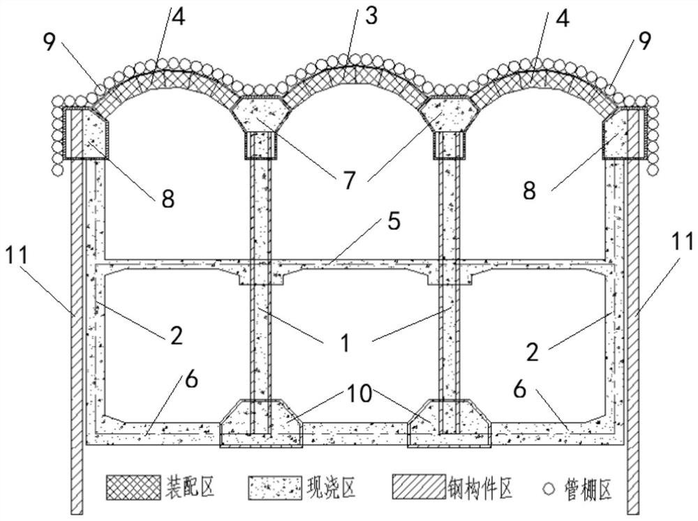
The invention relates to an integrated structure combining assembly and pouring for a mined metro station and a construction method thereof. The integrated structure combining assembly and pouring comprises a pipe shed, a vault, prefabricated parts, an intermediate load-bearing steel column, a side wall, a middle plate and a base plate, wherein the pipe shed is closely arranged by a plurality of steel pipes and a cross section forms a dome-shaped assembly, the top of the assembly is in a soil layer, the vault is tightly closed to the inner wall and arranged below the pipe shed; each prefabricated part comprises two first pilot tunnels, two positioning pilot tunnel and two second pilot tunnel; six prefabricated parts are respectively fixed by a pipe jacking method; the vault is composed ofa plurality of pipe segments, comprising a middle hole vault and a side hole vault, the intermediate load-bearing steel column is a steel pipe concrete structure, and the fixing installation is realized from the pilot tunnels above the intermediate load-bearing steel column to the positioning pilot tunnel; the side walls of the two sides pass through an auxiliary steel pipe structure, the jackingconstruction is carried out downwards from the second pilot tunnels above the side walls of the two sides and exceeds the base plate to extend in the ground; the intermediate plate, the base plate and the intermediate load-bearing steel column and the side wall are integrally poured and fixed to form the integrated structure combining assembly and pouring for the mined metro station.

Description

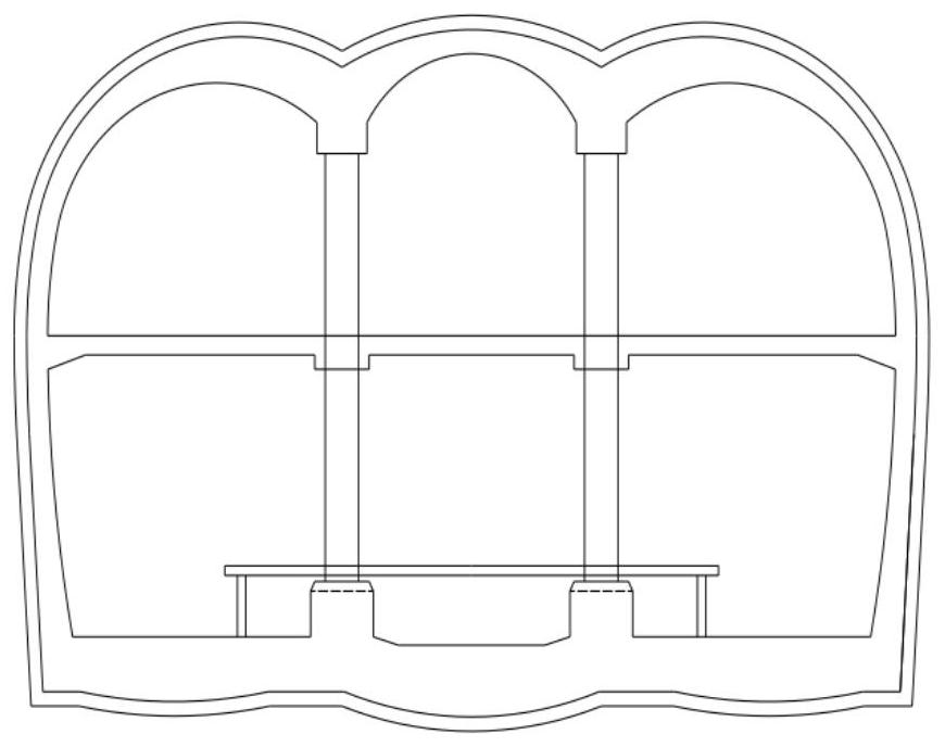
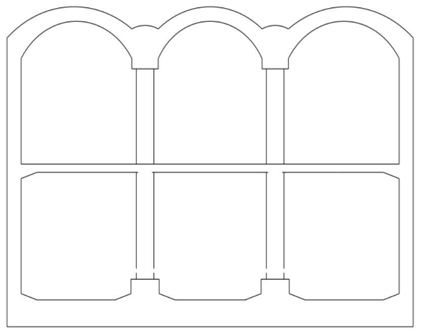
technical field [0001] The invention belongs to the technical field of subway underground excavation station construction, and in particular relates to a subway station underground excavation combined integrated structure and construction method. Background technique [0002] Faced with the current increase in the development of urban underground space and the increase in the scale of subway construction, the subway station, as the most important part of the entire subway line, is also the most difficult part of investment, design and construction, and is the main structure of passenger flow and transfer At the same time, it is also the part that involves the most difficulty in construction. figure 1 and figure 2 It is a schematic cross-sectional diagram of a typical subway station. It is generally a two-story, three-span structure, and there are also two-story, two-span structures and other forms. The construction methods of the station are mainly open-cut method, undergr...

Claims


Application Information

Patent Timeline
Patent Type & Authority Patents(China)
IPC IPC(8): E21D9/10E21D9/14E21D11/10E21D11/08E21D11/18
CPCE21D9/10E21D9/14E21D11/08E21D11/10E21D11/18
Inventor 康富中
Owner JIAN YAN FOUND ENG
Learn More