
Warm gas isolation device of subway channel

A channel and subway technology, applied in the field of thermal insulation devices for subway passages, can solve the problems of excessive rainwater, inability to drain away in time, waste of electric energy, etc., and achieve the effects of avoiding the loss of cold air, reducing energy consumption, and isolating the entry of hot air.

Active Publication Date: 2019-11-19
杭州叶蓁科技有限公司
View PDF7 Cites 6 Cited by
  • Summary
  • Abstract
  • Description
  • Claims
  • Application Information

AI Technical Summary

Problems solved by technology

[0003] At present, in the hot summer, the air conditioner is usually turned on in the subway station. People take the elevator to enter the subway passage through the subway entrance. Since the air-conditioning air is generated from the hall at the end of the subway passage, people walk to the subway passage and the subway passage after going down to the passage. At the junction of the hall, you can feel the obvious temperature difference, and the hot air in the subway passage will continuously enter the hall, so you need to increase the air output of the air conditioner to maintain a certain temperature, resulting in a waste of electric energy; and when it is raining At the same time, there is often a lot of rainwater remaining on the ground of the subway passage, which cannot be drained away in time.

Method used


Image

  • Warm gas isolation device of subway channel
  • Warm gas isolation device of subway channel
  • Warm gas isolation device of subway channel

Examples


Embodiment 1

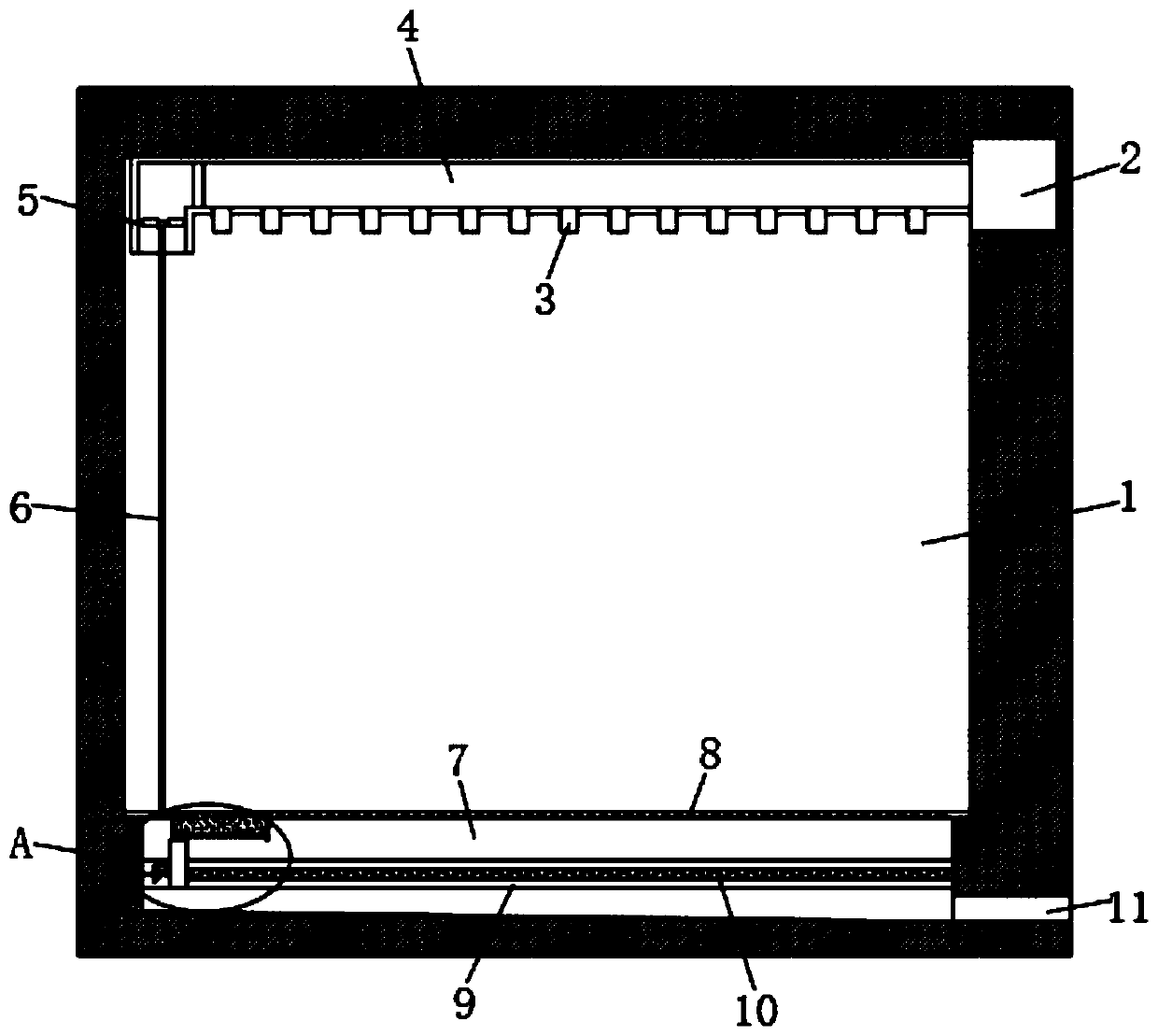
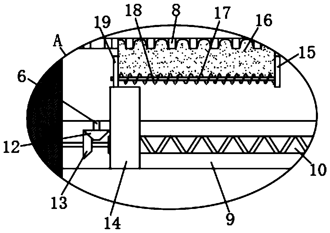
[0024] refer to Figure 1-4 , a warm insulation device for a subway passage, comprising a subway passage 1, a blower 2 is installed on the top of one side of the subway passage 1, the air outlet end of the blower 2 is connected with an air outlet pipe 4 extending along the top of the subway passage 1, and the air outlet pipe The lower end of 4 is provided with a plurality of air outlets 3 at equal intervals, and a solenoid valve is installed at the corner of the end of the air outlet pipe 4. The end of the air outlet pipe 4 is provided with a fan blade 5, and the middle part of the fan blade 5 is connected with a connecting shaft 6. The ground of channel 1 is provided with drainage groove 7, the bottom of drainage groove 7 is connected with drainage pipe 11, the notch of drainage groove 7 is covered with spacer 8, and the inner wall of drainage groove 7 is horizontally provided with installation groove 9, and the lower end of connecting shaft 6 Extending into the installation ...

Embodiment 2

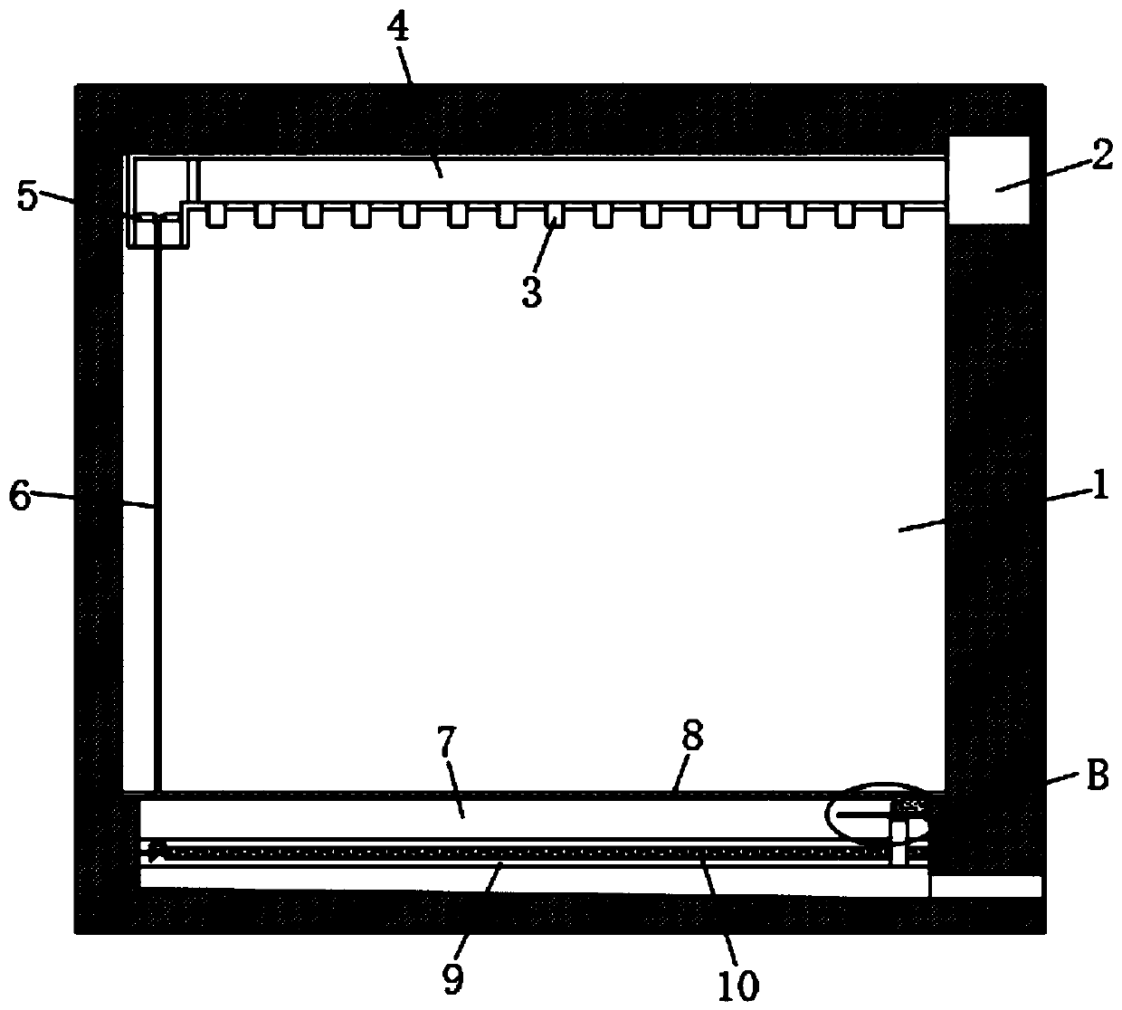
[0028] refer to Figure 5-6 , The difference between this embodiment and Embodiment 1 is that a device cavity 23 is provided in the lower end of the L-shaped slider 14, and a counter block 29 is provided in the device cavity 23, and the lower end of the counter block 29 is fixed with a hole that penetrates the device cavity 23. Connecting rod 28, the lower end of connecting rod 28 is fixed with push plate 25, and the upper end of block 29 is embedded with the first magnetic block 24, and the inner top of device chamber 23 is provided with the second magnetic block 24 different poles that attract each other. Magnetic block 22, the lower end of push plate 25 is embedded with the 3rd magnetic block 27, and the bottom left side of drain groove 7 is embedded with the 4th magnetic block 26 that repels with the 3rd magnetic block 27 same pole, the left side of drain groove 7 The bottom of the side is provided with a miscellaneous outlet 20, and the bottom of the right side of the dra...


PUM


Abstract

The invention discloses a warm gas isolation device of a subway channel. The warm gas isolation device of the subway channel involves the subway channel, the top of one side of the subway channel is provided with an air blower, the air outlet end of the air blower is connected with an air outlet pipe extending along the top of the subway channel, a plurality of air outlets are formed in the lowerend of the air outlet pipe at equal intervals, an electromagnetic valve is installed at the corner of the tail end of the air outlet pipe, fan blades are arranged in the tail end of the air outlet pipe, the fan blades are connected with a connecting shaft, the ground of the subway channel is provided with a drainage groove, the bottom of the drainage groove is connected with a drainage pipe, a notch of the drainage groove is covered with an isolation net, an installation groove is horizontally formed in the inner wall of the drainage groove, the lower end of the connection shaft extends into the installation groove, and the inner wall of the installation groove is rotationally connected with a reciprocating lead screw. The warm gas heat isolation device has the advantages that the structure is reasonable, an air curtain can be formed to isolate the hot gas, the electric energy required by refrigeration of an air conditioner can be reduced, and accumulated water on the isolation net canbe timely sucked away.

Description

technical field [0001] The invention relates to the technical field of subway stations, in particular to a warm insulation device for subway passages. Background technique [0002] A subway station is a place where railway trains stop for the urban rail transit system (referred to as the urban rail system) to carry goods or allow passengers to ride. A subway station usually has multiple entrances and exits to facilitate pedestrians without crossing the road Entering the station, for the convenience of passengers, elevators, stairs and elevators are generally installed between the lobby and the platform. The subway stations with a large span may even have electric flat walkways, which are generally installed for the comfort of passengers. Air Conditioning System. [0003] At present, in the hot summer, the air conditioner is usually turned on in the subway station. People take the elevator to enter the subway passage through the subway entrance. Since the air-conditioning ai...

Claims


Application Information

Patent Timeline
Patent Type & Authority Applications(China)
IPC IPC(8): F24F9/00F26B5/16A47L23/22
CPCA47L23/266F24F9/00F26B5/16
Inventor 张永东
Owner 杭州叶蓁科技有限公司
Learn More