Throttling component and refrigeration circulatory system
A technology of throttling parts and throttling parts, which is applied in the direction of fluid circulation arrangements, refrigerators, refrigeration components, etc., can solve the problems of low operational reliability and compact structure, high cost of processing and manufacturing components, and increased system operation complexity, etc. problem, achieve the effect of reducing size, increasing strength and improving balance
- Summary
- Abstract
- Description
- Claims
- Application Information
AI Technical Summary
Problems solved by technology
Method used
Image
Examples
Embodiment 1
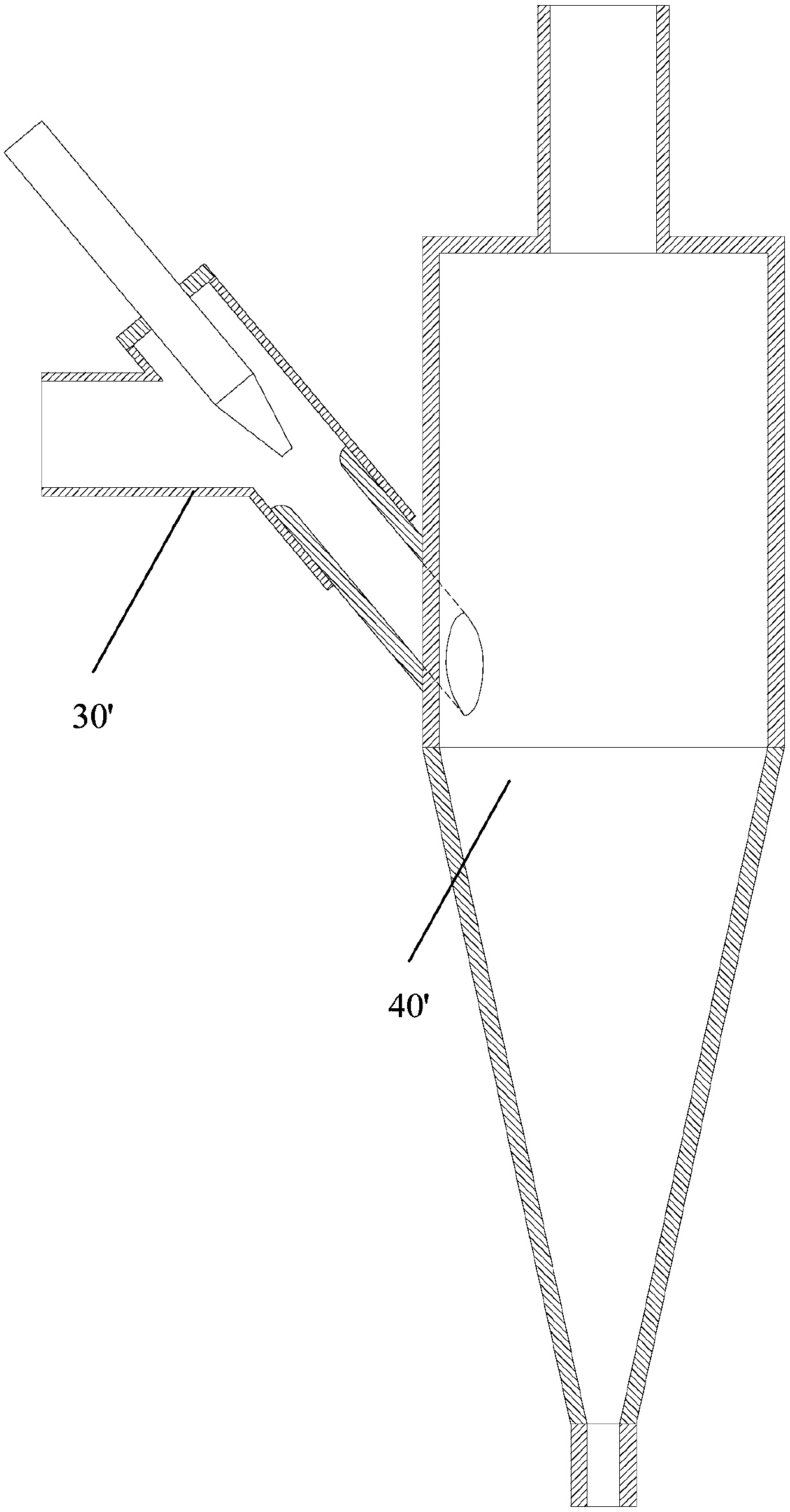
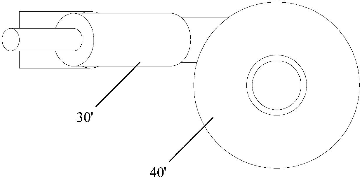
[0056] Such as Figure 4 As shown, the throttling component 3 according to an embodiment of the present invention includes: a fixedly connected injector 30 and a separator 32. The main body of the injector 30 has a throttling part 300, a diversion part 304 and a mixed flow The tee pipe of part 302, the end entrance of the throttling part 300 on the tee pipe is fixedly connected with a positioning end cap 306, and the positioning end cap 306 is covered on the end of the throttling part 300, and the positioning end cap 306 is A throttling tube 308 runs through, and the throttling tube 308 extends into the throttling part 300 through the positioning end cap 306; a mixing tube 303 is coaxially fixed in the mixing part 302, one end of the mixing tube 303 is fixedly connected with the mixing part 302, and the other end Stretch in the separator 32 from the end of the separator 32, the ejector 30 is fixedly connected with the end of the separator 32 by the flow mixing pipe 303; The m...
Embodiment 2
[0076] The throttling component 3 according to an embodiment of the present invention is modified on the basis of the first embodiment. The difference from Embodiment 1 is that the throttling tube 308 is replaced with an orifice.
[0077] Specifically, the positioning end cap 306 of this embodiment is provided with a throttling hole, and the throttle tube 308 is replaced by the throttling hole, thereby saving parts, reducing parts, simplifying the structure, simplifying the processing technology and installation process , improve work efficiency and reduce costs. Considering the length of the throttling tube 308, the orifice can be lengthened by thickening the positioning end cap 306, or the position of the orifice can be thickened separately so that the surface of the positioning end cap 306 is convex at the position of the orifice , thereby increasing the length of the orifice.
[0078] Another difference between this embodiment and Embodiment 1 is that the flow mixing pip...
Embodiment 3
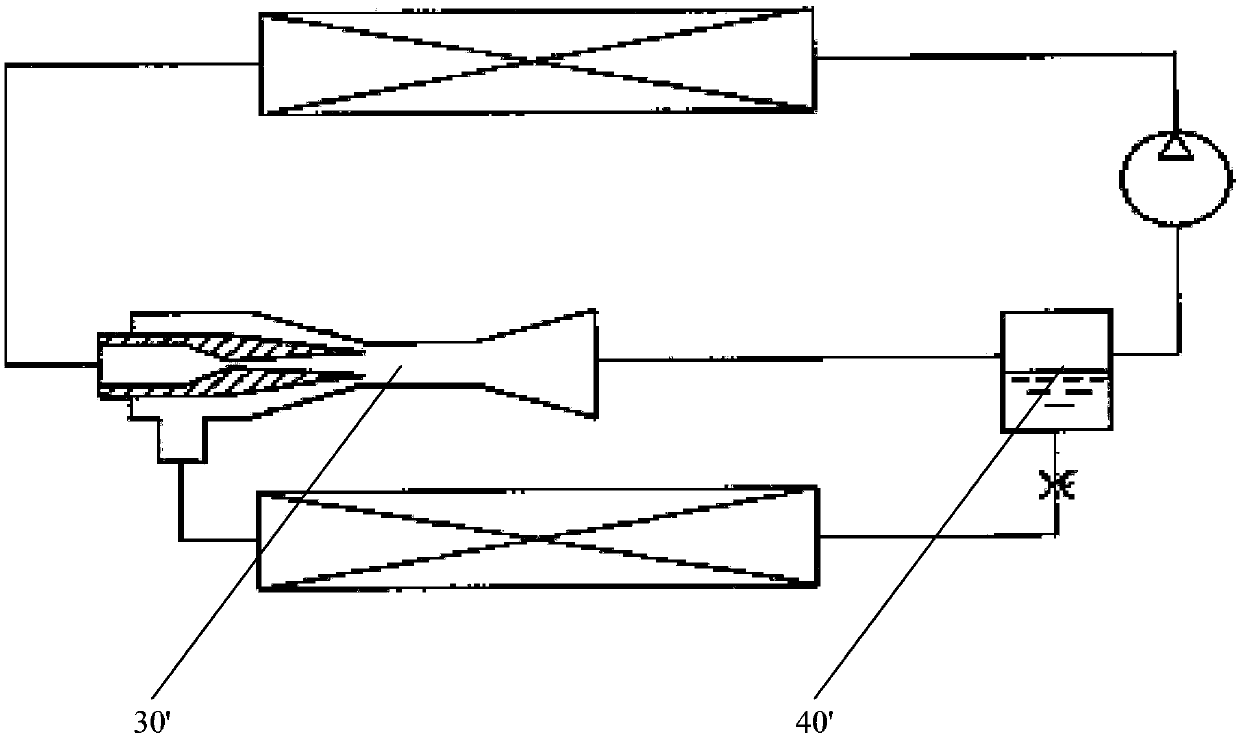
[0082] Such as Figure 5 As shown, the refrigeration cycle system of an embodiment proposed by the present invention adopts the throttling component 3 of any of the above-mentioned embodiments, including: a compressor 1, a condenser 2, a throttling component 3, an evaporator 4, and a regenerator 5 , The throttling part 3 is placed between the circulating regenerator 5 and the evaporator 4, and the refrigerant realizes multiple processes such as throttling, drainage pressurization, and gas-liquid separation in the throttling part 3 .
[0083] By adopting the throttling component 3 of any one of the above-mentioned embodiments, all the beneficial effects of the above-mentioned embodiments are obtained, and details are not repeated here.
[0084] The technical solution of the present invention has been described in detail above in conjunction with the accompanying drawings. Through the technical solution of the present invention, multiple functions such as throttling, drainage an...
PUM
 Abstract
Description
Claims
Application Information
 - R&D
- Intellectual Property
- Life Sciences
- Materials
- Tech Scout
- Unparalleled Data Quality
- Higher Quality Content
- 60% Fewer Hallucinations
Browse by: Latest US Patents, China's latest patents, Technical Efficacy Thesaurus, Application Domain, Technology Topic, Popular Technical Reports.
© 2025 PatSnap. All rights reserved.Legal|Privacy policy|Modern Slavery Act Transparency Statement|Sitemap|About US| Contact US: help@patsnap.com


