Baling device

A technology of a baling device and a material channel, which is applied in the direction of balers, cutters, agricultural machinery and implements, etc., can solve the problems of straw being susceptible to external vibration, wind direction, inability to effectively protect functional components, and low straw pushing efficiency, etc. Achieve the effect of strength and firmness guarantee, stable force, and improved transmission performance

Pending Publication Date: 2019-11-22
XINGGUANG AGRI MACHINERY
View PDF2 Cites 3 Cited by
  • Summary
  • Abstract
  • Description
  • Claims
  • Application Information

AI Technical Summary

Problems solved by technology

The defect of this blanking method is that the straw is not pushed to the pusher execution part centrally, so that the push efficiency of the straw is not high, and the straw is easily affected by external vibration, wind direction, etc., and some of the straw will be scattered and cannot be pushed to the pusher by the pusher execution part. Bundle area; at the same time, this tying mechanism has no other device to protect parts so that it cannot effectively protect functional parts in case of failure
For example, CN201810844275.1 in the prior art discloses a crawler self-propelled baler. Although it is disclosed that the two sprockets of the feeding mechanism are fixed on the feeding bin, one end of the near connecting rod and the far connecting rod are separately installed on the two chains. On the wheel, one end is divided into the close crank and the far crank, and the other ends of the close crank and the far crank are respectively connected to the close rocker and the far rocker; the near rocker and the far rocker are separately installed on the baling chamber and the feeding bin. , but no detailed structural settings are given, and it is not clear about the effect of its specific material adjustment

Method used


Image

  • Baling device
  • Baling device
  • Baling device

Examples


Embodiment Construction

[0058] The present invention will be described in further detail below according to the drawings and embodiments.

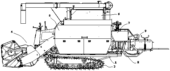
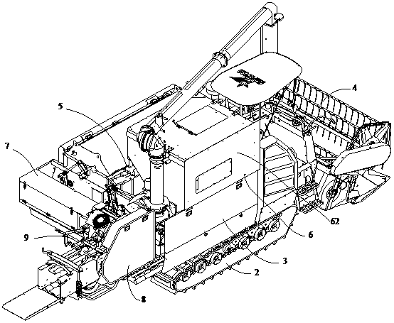
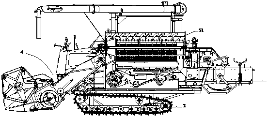
[0059] refer to Figure 1-Figure 19 , a harvesting and bundling integrated machine, which includes a bottom frame 1, a traveling mechanism 2, a power transmission device 3, a harvesting device, and a bundling device. Wherein the harvesting device comprises a header mechanism 4, a threshing mechanism 5, and a grain harvesting mechanism 6. And the bundling device comprises feeding mechanism 7, material pushing mechanism 8, bundling mechanism 9.

[0060] Bottom frame 1 and running gear 2 are prior art, and running gear is the structure of crawler self-propelled type, and its main function part is driving wheel, other functional wheels such as guide wheel, tensioner wheel and drive track. The power transmission device 3 also belongs to the prior art, and what it adopts is a diesel engine. The power of the diesel engine that usually reaches the power matching can be...


PUM


Abstract

The invention discloses a baling device. The baling device comprises a push mechanism, a feeding mechanism and a baling mechanism, wherein the push mechanism comprises a push channel used for containing to-be-baled straw, a push swing arm which does fixed-axis rotation, a push rod and a push part, the two ends of the push rod are hinged to the push swing arm and the push part respectively, and thepush part is driven by the push rod to do reciprocating motion along the push channel; the feeding mechanism comprises a feeding channel which is vertically communicated with the push channel and atleast one poking mechanism, the communication portion of the feeding channel and the push channel is located on a moving path of the push part, and the poking mechanisms are used for pushing the strawin the feeding channel into the push channel; the baling mechanism is located at the output end of the pushing channel. The baling device has the advantage that the arrangement of the space structures is reasonable, the threshing and baling efficiency of the integrated machine is high, the effect is good, and a straw bale which is thrown out is located on a walking track.

Description

technical field [0001] The invention relates to a bundling device, which is mainly used in the technical field of equipment for harvesting and cleaning straw of cereal crops. Background technique [0002] With the continuous improvement of the level of agricultural mechanization in our country, the application of grain harvesters is becoming more and more extensive. In the prior art, for the bundling device, the throwing direction of most straws after bundling is perpendicular to the walking direction, that is, the bundled straws are arranged beside the walking track, so the actual working width range is relatively large, which is not conducive to space utilization . When bundling, straws are usually conveyed directly into a mechanism for pushing and bundling. For example, the prior art CN201820289024.7 discloses a pushing and bundling mechanism for a bundling machine. Both the bottom and the side of the pushing actuator are provided with a second pulley that is connected ...

Claims


Application Information

Patent Timeline
Patent Type & Authority Applications(China)
IPC IPC(8): A01D37/00A01D41/12A01D61/00
CPCA01D37/00A01D41/12A01D61/00
Inventor 邱扬扬冯涛金鑫
Owner XINGGUANG AGRI MACHINERY
Why Eureka
Try Eureka