A cutting fluid recycling mechanism for machine tools

A cutting fluid and machine tool technology, which is applied in the field of machine tool cutting fluid recycling mechanism, can solve problems affecting electromagnet recovery, uneven dispersion performance, debris accumulation, etc., to improve uniformity, reduce metal debris content, reduce The effect of the jam probability

Active Publication Date: 2021-05-28
苏州市业成精密机械有限公司
View PDF9 Cites 0 Cited by
  • Summary
  • Abstract
  • Description
  • Claims
  • Application Information

AI Technical Summary

Problems solved by technology

This device can efficiently filter out the metal debris in the cutting fluid and improve the recycling rate of the cutting fluid”, but there are still defects. The dispersion performance of the waste liquid containing chips and debris entering the filter screen is uneven, and the waste liquid falls into the filter screen. Concentrated location of the net can lead to accumulation of debris, affecting the recovery of the electromagnet

Method used


Image

  • A cutting fluid recycling mechanism for machine tools
  • A cutting fluid recycling mechanism for machine tools
  • A cutting fluid recycling mechanism for machine tools

Examples


Embodiment Construction

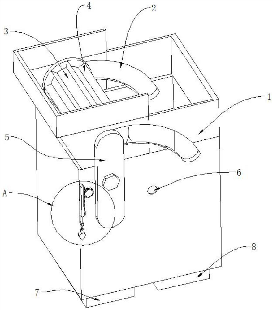
[0039]Such asFigure 1 to 6The cutting solution reuse mechanism shown is shown, including the tape opening of the case, and also includes a separator 14, connected to the inner side wall of the casing 1, separated into a waste liquid cavity and scrap cavity, and the separator There is a slot on 14 on 14;

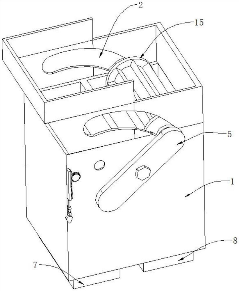
[0040]The tank 2 is adjusted to the outer wall of the box 1;

[0041]The adjustment board 5 is rotatably connected to the outer side wall of the box 1;

[0042]The mounting hole 6 is opened in the outer wall of the casing 1;

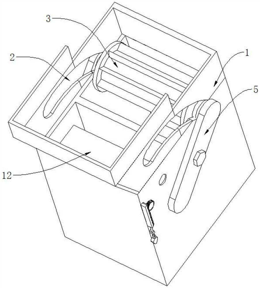
[0043]The drive roller 3 is connected between the adjustment plate 5 by a connecting shaft disposed within the adjustment groove 2;

[0044]The electromagnet adsorption plate 4 is uniformly disposed on the outer side wall of the drive roller 3;

[0045]The blaming plate 12 is rotated by the rotation shaft to be attached to the inner side wall of the casing 1, and placed in the waste liquid chamber;

[0046]The first reciprocating adjustment assembly, the drive end of the first re...


PUM


Abstract

The invention discloses a cutting fluid recycling mechanism for a machine tool, comprising a box body with an open top, and a partition plate, which is connected to the side wall of the box body, and divides the box body into a waste liquid cavity and a waste chip cavity. A slot is provided; an adjustment slot is opened on the outer side wall of the box body; an adjustment plate is rotatably connected to the outer side wall of the box body; a mounting hole is opened on the outer side wall of the box; It is connected between the adjustment plates; the electromagnet adsorption plate is evenly arranged on the outer side wall of the driving roller; the blanking plate is connected to the inner side wall of the box body through the rotating shaft, and is placed in the waste liquid chamber; the first reciprocating adjustment component , the driving end of the reciprocating adjustment component is connected with the rotating shaft; the cutting fluid recycling mechanism for machine tools of the present invention realizes the pretreatment function of cutting waste fluid, reduces the debris content when the cutting waste fluid falls into the filter plate, and at the same time the filter plate During the filtration process, the metal debris on the filter plate is adsorbed, which improves the continuous performance of the filter plate.

Description

Technical field[0001]The present invention relates to a cutting solution for a machine tool, which belongs to the technical field of machine tool.Background technique[0002]Cutting fluid is an industrial liquid for cooling and lubricating tools and processing components during metal cutting and grinding. The cutting fluid is formed by a variety of super-function auxiliary compounds, and has a good Cooling performance, lubrication performance, anti-rust performance, anti-oil cleaning function, anti-corrosion function, easy dilution character, overcome traditional saponi emulsion summer volatile, difficult to dilute, rust and rust effect, there is no Adverse effects, suitable for cutting and grinding of black metals, is the most leading grinding product, all of which are better than saponified oil, which has good cooling, cleaning, anti-rust, etc., and has non-toxic , Odorless, there is no erosion of the human body, the equipment is not corrosive, and the environment is not polluting.[...

Claims


Application Information

Patent Timeline
Patent Type & Authority Patents(China)
IPC IPC(8): B23Q11/10
CPCB23Q11/1069Y02P70/10
Inventor 范荣华
Owner 苏州市业成精密机械有限公司
Why Eureka
Try Eureka