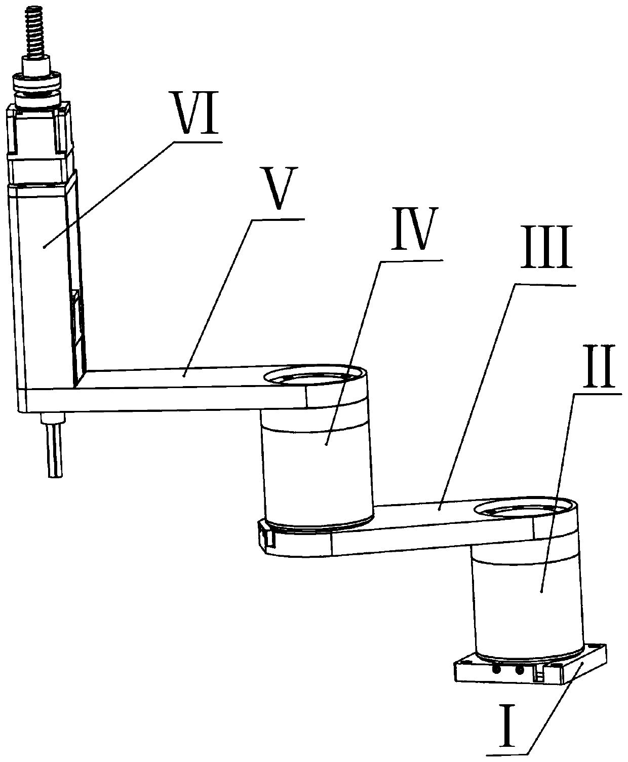
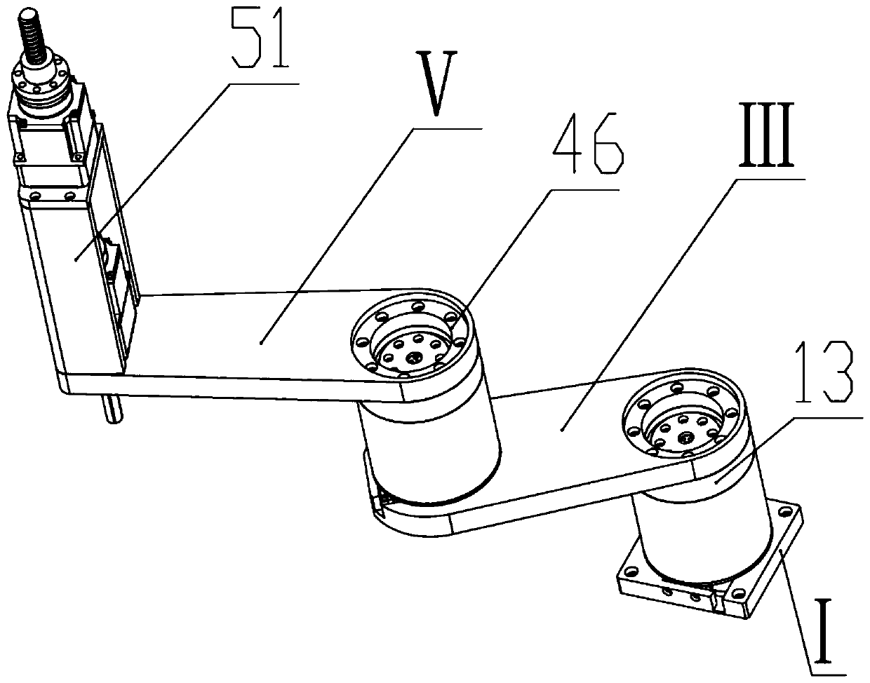
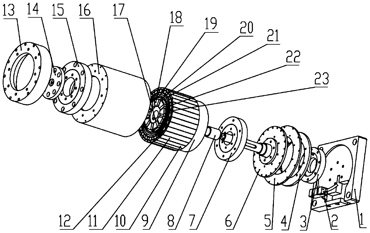
Plane joint type robot and outer rotor joint device

A technology of planar joints and external rotors, applied in the direction of manipulators, program-controlled manipulators, joints, etc., can solve problems such as errors, small torque density, and affecting assembly accuracy, and achieve low cost, reduced volume, and simple and compact structure.

Inactive Publication Date: 2019-11-22
刘吉柱
View PDF4 Cites 2 Cited by
  • Summary
  • Abstract
  • Description
  • Claims
  • Application Information

AI Technical Summary

Problems solved by technology

However, due to the use of a harmonic reducer or RV reducer, and there is a backlash between the meshing teeth in the reducer, there will be inevitable errors when the planar articulated robot arm is working, which will affect the assembly accuracy, and the torque density is relatively low. Small

Method used


Image

  • Plane joint type robot and outer rotor joint device
  • Plane joint type robot and outer rotor joint device
  • Plane joint type robot and outer rotor joint device

Examples


Embodiment Construction

[0028] In order to enable those skilled in the art to better understand the technical solutions in the present invention, the technical solutions in the embodiments of the present invention will be clearly and completely described below in conjunction with the drawings in the embodiments of the present invention. Obviously, the described The embodiments are only some of the embodiments of the present invention, not all of them. Based on the embodiments of the present invention, all other embodiments obtained by persons of ordinary skill in the art without making creative efforts shall fall within the protection scope of the present invention.

[0029] In describing specific embodiments of the present invention, the terms "upper", "lower", "front", "rear", "left", "right", "vertical", "horizontal", "bottom", "inner The orientation or positional relationship indicated by "" and "outside" are based on the orientation or positional relationship shown in the drawings, and usually r...


PUM


Abstract

The invention discloses a plane joint type robot and an outer rotor joint device. The robot comprises a base, a first outer rotor joint device, a first mechanical arm and a mechanical hand, wherein the first outer rotor joint device is arranged at the base, the first mechanical arm is driven by the the first outer rotor joint device, and the mechanical hand is connected with the first mechanical arm; the first outer rotor joint device comprises a fixed shaft, a stator iron core, a motor coil, an inner rotor component, an outer rotor component and a magnetism adjusting ring, wherein the fixed shaft is fixed relative to the base and extends along the longitudinal axis, the stator iron core is fixedly arranged on the fixed shaft, the motor coil is wound on the stator iron core, the inner rotor component is located on the periphery of the motor coil, the outer rotor component is located on the periphery of the inner rotor component, and the magnetism adjusting ring is located between the inner rotor component and the outer rotor component in the circumferential direction; and the first mechanical arm is fixedly connected with the outer rotor component, and certain gaps are formed between the inner rotor component, the magnetism adjusting ring and the outer rotor component in the circumferential direction. According to the robot and the device, the precision of transmission is high,the utilization rate of a permanent magnet is high, the structure is simple and compact, and the cost is low.

Description

technical field [0001] The invention relates to a plane joint type robot and an outer rotor joint device. Background technique [0002] With the rapid development of IC, semiconductor, and 3C industries, modern automated factories continue to upgrade, industrial robots will be more widely used in various fields of manufacturing, and the requirements for robots in the field of precision assembly are getting higher and higher. Traditional SCARA robots have already It is difficult to meet the demand for robot speed and precision in assembly operations, and there is an urgent need to improve robot performance. The existing planar articulated robot arm joints are connected through a harmonic reducer or RV reducer, and the reducer is driven by a servo motor to achieve the purpose of quickly driving the mechanical arm. However, due to the use of a harmonic reducer or RV reducer, and there is a backlash between the meshing teeth in the reducer, there will be inevitable errors when ...

Claims


Application Information

Patent Timeline
Patent Type & Authority Applications(China)
IPC IPC(8): B25J9/04B25J9/12B25J17/02
CPCB25J9/042B25J9/126B25J17/0258
Inventor 刘吉柱
Owner 刘吉柱
Why Eureka
Try Eureka